
Related Manuals for ENMET CO-Guard


Summary of Contents for ENMET CO-Guard
- Page 1 ENMET 680 Fairfield Court Ann Arbor, MI 48108 734.761.1270 Fax 734.761.3220 www.enmet.com CO-Guard Compressed Air Line CO Monitor Operation Manual...
-
Page 2: Table Of Contents
Figure 3: Mounting CO-Guard ..............................6 Figure 4: Power Terminal Connections CO-Guard ........................7 Figure 5: Relay Terminal Connections CO-Guard ........................8 Figure 6: CO-Guard Maintenance Menu Flow Chart ........................ 12 Figure 7: Calibration Adapter ..............................13 Figure 8: CO-Guard Sensor Replacement ..........................17... -
Page 3: Introduction
The CO-GUARD is a compressed air monitoring instrument that measures and detects Carbon Monoxide (CO) in industrial compressed breathing air systems utilizing an electrochemical sensor. The CO-GUARD is NOT in an enclosure rated for use in a Class I, Div. 1, Groups B, C, D classified area and CAN NOT be installed in a hazardous location. -
Page 4: Components Of The Co-Guard
CO-Guard ENMET 2.0 Components of the CO-G UARD 2.1 CO-G elements UARD See Figure 1 for location of elements: Feature Description Enclosure A polycarbonate box, approximately 7 x 5 x 3, with a detachable front cover. 4 holes for mounting the enclosure to a vertical surface. Located at the corners of the bottom of the enclosure, directly beneath the 4-front cover retaining screws. -
Page 5: Figure 1A: Optional Regulator And Sample Air Hose
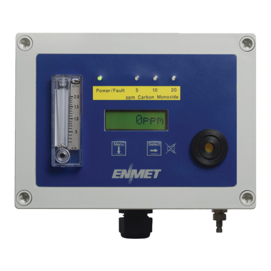
CO-Guard ENMET Visual Indicator Visual Indicators: Alarm1, Alarm2, Alarm3 Pushbutton Switches Menu Select Audio Alarm Flowmeter Front Cover Retaining Screws 4 places Strain Relief Input Port Figure 1: External CO-G Features UARD Regulator Female Quick Release Fitting to Inlet Port ¼“... -
Page 6: Circuit Board Features
CO-Guard ENMET 2.3 Circuit Board Features The Display Panel is attached by a cable and is released by unscrewing the 4 screws located in the corners. After releasing the panel, it is swung upward, exposing the interior of the enclosure. The Circuit Board is mounted at the back surface of the enclosure interior. -
Page 7: Installation
CO-Guard ENMET 3.0 Installation The CO-G should be located near the pipe or tank containing the air to be monitored, and upstream from where the air is being UARD used. The CO-G must be installed such that it samples the compressed air before it reaches the users. -
Page 8: Wiring The Co-Guard
3.2 Wiring the CO-G UARD The electrical installation should conform to appropriate electrical codes, such as the National Electrical Code in the United States. : The compliance of the installation to appropriate codes is not ENMET’s responsibility. ARNING The CO-G should be powered through circuit breakers provided for this purpose. -
Page 9: Relay Contacts
CO-Guard ENMET 3.2.3 Relay Contacts Relay contacts are available for each alarm; these are SPDT, rated at 10Amp at 110V , and may be latching or non-latching as required by the application. They are accessed on the terminals next to each relay see Figure 5. The contact positions are noted on the circuit board next to each terminal. -
Page 10: Operation
CO-Guard ENMET 4.0 Operation When the CO-G is installed as described in Section 3, and in clean air, the POWER green LED is on, the display is lit and the UARD information on the display is measurement of carbon monoxide detected by the CO-G . -
Page 11: Normal Display Mode
CO-Guard ENMET 4.2 Normal Display Mode When the CO-G is installed as described in section 3, and in clean air, the POWER green LED is on, the display is lit and the UARD information on the display is measurement of carbon monoxide detected by the CO-G . -
Page 12: Maintenance
CO-Guard ENMET 5.0 Maintenance The CO-G maintenance menus that are accessed by pressing the M button and entering a valid access code. The access UARD code is set at the factory and may be changed by following the access code menu explained in section 5.5. -
Page 13: Figure 6: Co-Guard Maintenance Menu Flow Chart
Zero Press the S button to initiate Zero adjustment ELECT If the Zero signal is within Preset Specs the CO-Guard will display Cal Cal OK OK, See Section 5.2.2 Bad ZERO If the Zero signal is not within Preset Specs the CO-Guard will display... -
Page 14: Calibration Of The Co-Guard
ENMET recommends at least quarterly calibration of the CO-G instrument. UARD Calibration equipment is available from ENMET to calibrate the CO-G instrument. UARD •Calibration adapter, a length of tubing with a regulator for the gas cylinder on one end, and a quick release fitting to connect to the sample input of the CO-G on the other. -
Page 15: Exit Maintenance Menu
Zero adjustment ELECT Zero If the Zero signal is within Preset Specs the CO-Guard will Cal OK display Cal OK momentarily then advance to Span menu If the Zero signal is not within Preset Specs the CO-Guard... -
Page 16: Gas Span
CO-Guard ENMET 5.2.3 Gas Span It is recommended that the Zero Function be performed first. Do not perform a calibration unless span gas is applied to sensor. Calibration can be aborted by pressing and holing the M button for 3 – 4 seconds. -
Page 17: Alarm Set Points
CO-Guard ENMET 5.2.4 Alarm Set Points The CO-G alarm set points can be changed within limits. See Table 4 for factory set alarm points. UARD To change any of the three alarm points: Enter the maintenance menu as shown in Figure 6 CO-G Maintenance Menu flow chart. -
Page 18: Sensor Replacement
If you do not know the proper part number for your sensor, have the CO-G serial number available when UARD contacting your Distributor or ENMET Technical Support. Remove, the 4 retaining screws from CO-G lid and 2 retaining screws form sensor manifold, see Figure 6 UARD ... -
Page 19: Replacement Parts
CO-Guard ENMET 6.0 Replacement Parts ENMET replacement part numbers: Description of Part Part Number Sensor CO 67025-1200 Calibration Regulator, for 17 liter, cylinder 03700-500 Calibration gas, 20ppm CO, 17 liter 03219-020 Zero Gas, 20.9% O2, 17 liter 03296-209 Aerosol gas, 20ppm CO 03101-020 Aerosol gas, 20.9% O2... - Page 20 ENMET, LLC for damages arising out of or in connection with the use or repair or performance of the product.
- Page 21 ENMET charges a one hour minimum billing for all approved repairs with additional time billed to the closest tenth of an hour. All instruments sent to ENMET are subject to a minimum evaluation fee, even if returned unrepaired.
- Page 22 Mailing/Shipping Address: ENMET 680 Fairfield Court Ann Arbor, MI 48108 Phone: 734.761.1270 repair@enmet.com Fax: 734.761.3220 Service Request Form Product Name or Number: Product Serial Number: Describe Problem or Needed Service: Warranty Claim? ☐ Yes ☐ No CUSTOMER INFORMATION Billing Address:...
Need help?
Do you have a question about the CO-Guard and is the answer not in the manual?
Questions and answers