
Related Manuals for ENMET CO-GUARD


Summary of Contents for ENMET CO-GUARD
- Page 1 ENMET ENMET ENMET ENMET Corporation PO Box 979 Ann Arbor, MI 48106-0979 CO-G UARD Compressed Air Line CO Monitor Manual 80002-044 April 2006 MCN-347, 05/18/06...
-
Page 3: Table Of Contents
Table of Contents 1.0 INTRODUCTION ................................1 1.1 U ..................................1 NPACK 1.2 C ................................1 HECK RDER 1.3 S ................................1 ERIAL UMBERS 2.0 COMPONENTS OF THE CO-GUARD........................2 2.1 CO-G ..............................2 UARD ELEMENTS 2.2 CO-G ..........................2 UARD PERATIONAL EATURES 2.3 C ............................4 IRCUIT OARD EATURES 3.0 INSTALLATION .................................5... -
Page 5: Introduction
If you need your shipments insured, please forward a written request to ENMET Customer Service. Regarding Shortages If there are any shortages or questions regarding this shipment, please notify ENMET Customer Service within 5 days of receipt at the following address: ENMET Corporation... -
Page 6: Components Of The Co-Guard
ENMET Corporation CO-G UARD 2.0 Components of the 2.0 Components of the 2.0 Components of the 2.0 Components of the CO-G UARD 2.1 CO-G elements UARD See Figure 1 for location of elements: Feature Description Enclosure A polycarbonate box, approximately 7 x 5 x 3, with a detachable front cover. -
Page 7: Figure 1: External Co-Guard Features
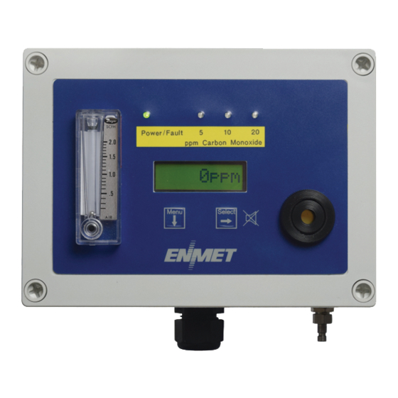
CO-G ENMET Corporation UARD Visual Indicator Visual Indicators: Power/Fault Alarm1, Alarm2, Alarm3 Pushbutton Switches Menu Select Audio Alarm Flowmeter Front Cover Retaining Screws 4 places Strain Relief Input Port Figure 1: External CO-G Features UARD Regulator Female Quick Release Fitting to Inlet Port ¼“... -
Page 8: Circuit Board Features
ENMET Corporation CO-G UARD 2.3 Circuit Board Features The Display Panel is attached by a cable and is released by unscrewing the 4 screws located in the corners. After releasing the panel, it is swung upward, exposing the interior of the enclosure. The Circuit Board is mounted at the back surface of the enclosure interior. -
Page 9: Installation
CO-G ENMET Corporation UARD 3.0 Installation 3.0 Installation 3.0 Installation 3.0 Installation The CO-G should be located near the pipe or tank containing the air to be monitored, and upstream from where UARD the air is being used. The CO-G... -
Page 10: Wiring The Co-Guard
UARD The electrical installation should conform to appropriate electrical codes, such as the National Electrical Code in the United States. The compliance of the installation to appropriate codes is not ENMET’s responsibility. ARNING The CO-G should be powered through circuit breakers provided for this purpose. -
Page 11: Relay Contacts
CO-G ENMET Corporation UARD 3.2.3 Relay Contacts Relay contacts are available for each alarm; these are SPDT, rated at 10Amp at 110V , and may be latching or non- latching as required by the application. They are accessed on the terminals next to each relay see Figure 5. The contact positions are noted on the circuit board next to each terminal. -
Page 12: Operation
ENMET Corporation CO-G UARD 4.0 Operation 4.0 Operation 4.0 Operation 4.0 Operation When the CO-G is installed as described in Section 3, and in clean air, the POWER green LED is on, the UARD display is lit and the information on the display is measurement of carbon monoxide detected by the CO-G . -
Page 13: Normal Display Mode
CO-G ENMET Corporation UARD 4.2 Normal Display Mode When the CO-G is installed as described in section 3, and in clean air, the POWER green LED is on, the display UARD is lit and the information on the display is measurement of carbon monoxide detected by the CO-G . -
Page 14: Maintenance
ENMET Corporation CO-G UARD 5.0 Maintenance 5.0 Maintenance 5.0 Maintenance 5.0 Maintenance The CO-G maintenance menus that are accessed by pressing the M button and entering a valid access code. UARD The access code is set at the factory and may be changed by following the access code menu explained in section 5.5. -
Page 15: Figure 6: Co-Guard Maintenance Menu Flow Chart
ELECT If the Zero signal is within Preset Specs the CO-Guard will Cal OK display Cal OK, See Section 5.2.2 If the Zero signal is not within Preset Specs the CO-Guard will Bad ZERO display Bad ZERO ELECT You can Press and H... -
Page 16: Calibration Of The Co-Guard
ENMET Corporation recommends at least quarterly calibration of the CO-G instrument. UARD Calibration equipment is available from ENMET Corporation to calibrate the CO-G instrument. UARD •Calibration adapter, a length of tubing with a regulator for the gas cylinder on one end, and a quick release fitting to connect to the sample input of the CO-G on the other. -
Page 17: Exit Maintenance Menu
Zero adjustment ELECT Zero If the Zero signal is within Preset Specs the CO-Guard will Cal OK display Cal OK momentarily then advance to Span menu If the Zero signal is not within Preset Specs the CO-Guard... -
Page 18: Gas Span
ENMET Corporation CO-G UARD 5.2.3 Gas Span It is recommended that the Zero Function be performed first. Do not perform a calibration unless span gas is applied to sensor. Calibration can be aborted by pressing and holing the M button for 3 – 4 seconds. -
Page 19: Alarm Set Points
CO-G ENMET Corporation UARD 5.2.4 Alarm Set Points The CO-G alarm set points can be changed within limits. See Table 4 for factory set alarm points. UARD To change any of the three alarm points: Enter the maintenance menu as shown in Figure 6 CO-G Maintenance Menu flow chart. -
Page 20: Sensor Replacement
Section 6.0 of this manual. If you do not know the proper part number for your sensor, have the CO-G serial UARD number available when contacting your Distributor or ENMET Corporation Technical Support. Remove, the 4 retaining screws from CO-G lid and 2 retaining screws form sensor manifold, see Figure 6 UARD Remove, the sensor assembly from the PCB/sensor manifold, see Figure 8. -
Page 21: Replacement Parts
CO-G ENMET Corporation UARD 6.0 Replacement Parts 6.0 Replacement Parts 6.0 Replacement Parts 6.0 Replacement Parts ENMET replacement part numbers: Description of Part Part Number Sensor CO 67025-1200 Calibration Regulator, for 17 liter, cylinder 03700-500 Calibration gas, 20ppm CO, 17 liter 03219-020 Zero Gas, 20.9% O2, 17 liter... -
Page 22: Warranty
8.0 WARRANTY 8.0 WARRANTY ENMET warrants new instruments to be free from defects in workmanship and material under normal use for a period of one year from date of shipment from ENMET. The warranty covers both parts and labor excluding instrument calibration and expendable parts such as calibration gas, filters, batteries, etc... - Page 23 734.761.1270 Fax 734.761.3220 Returning an Instrument for Repair ENMET instruments may be returned to the factory or any one of our Field Service Centers for regular repair service or calibration. The ENMET Repair Department and Field Service Centers also perform warranty service work.
- Page 25 K ND Air Saver K 2-Day Air K Federal Express: K Ground K Express Saver K P-1 K Standard K 2-Day Air K FedEx Account number: ________________________ Would you like ENMET to insure the return shipment? K No K Yes Insurance Amount: $_________________...
Need help?
Do you have a question about the CO-GUARD and is the answer not in the manual?
Questions and answers