Dukane iQ Series User Manual
Ultrasonic welder
Hide thumbs
Also See for iQ Series:
- User manual (178 pages) ,
- Quick start manual (30 pages) ,
- Application note (16 pages)
Chapters
Table of Contents

Related Manuals for Dukane iQ Series


Summary of Contents for Dukane iQ Series
- Page 1 Series ULTRASONIC WELDER i220 Servo User’s Manual Dukane Part No. 403-601-00 Dukane • 2900 Dukane Drive • St. Charles, Illinois 60174 USA • TEL (630) 797- 4900 Dukane products are manufactured in ISO registered facilities www.dukane.com...
- Page 2 Printed in the United States of America. Dukane Part Number: 403-601-00 Dukane ultrasonic equipment is manufactured under one or more of the following U.S. Patents: 3,772,538 3,780,926 3,825,481 3,832,019...
- Page 3 Revision History Revision Revision Number Summary Date - 00 Original Release June 26, 2019 Page iii Dukane Manual Part No. 403-601-00...
- Page 4 Servo Ultrasonic Welder User’s Manual This page intentionally left blank Page iv Dukane Manual Part No. 403-601-00...
-
Page 5: Table Of Contents
Section 8 - System Operational Test .....81 Section 9 - Operation In Automation .....89 Section 10 - Specifications ........97 Section 11 - Maintenance ........105 Section 12 - Troubleshooting ....... 113 Section 13 - Contacting Dukane ......133 Index ...............137 Page v Dukane Manual Part No. 403-601-00... - Page 6 Servo Ultrasonic Welder User’s Manual This page intentionally left blank Page vi Dukane Manual Part No. 403-601-00...
- Page 7 Key i220 Servo Features . . . . . . . . . . . . . . . . . . . . . . . . . . . . 5 Page 1 Dukane Manual Part No. 403-601-00...
- Page 8 Servo Ultrasonic Welder User’s Manual This page intentionally left blank Page 2 Dukane Manual Part No. 403-601-00...
-
Page 9: Section 1 - Introduction
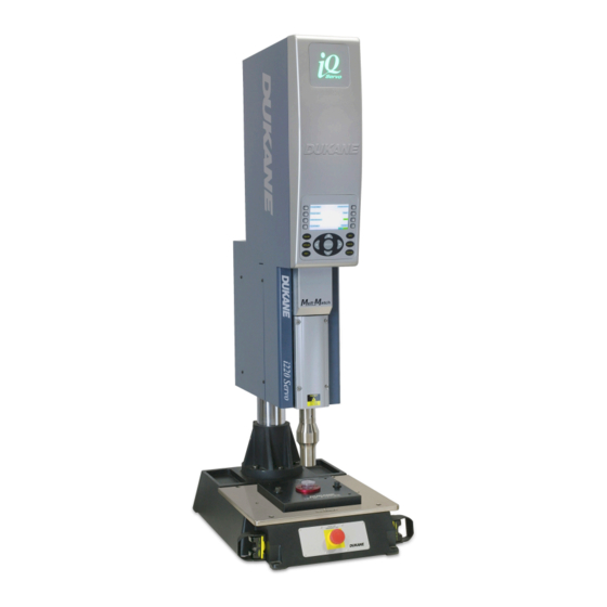
(e.g. –I, –II, –III). As an example, Figure 3–2 would be the second illustration in section three while Table 3—II would be the second table in section three. Condition Electrical Hot Surface Or Practice Hazard Page 3 Dukane Manual Part No. 403-601-00... - Page 10 Servo Ultrasonic Welder User’s Manual 220 Servo Ultrasonic Welder Overview The iQ Series i220 Integrated Servo Driven Ultrasonic Welder with patented Melt-Match® technology is a self- contained unit with iQ Series Generator/Power Supply housed within the press. In a smaller footprint, the i220...
- Page 11 The i220 Servo system provides the following major features: • Repeatable and accurate servo motion control • Integrated Melt-Match® technology • Dynamic Velocity Melt Initiation (DVMI™) • Programmable stack velocity and location control • Integrable into automated assembly systems Page 5 Dukane Manual Part No. 403-601-00...
- Page 12 Servo Ultrasonic Welder User’s Manual This page intentionally left blank Page 6 Dukane Manual Part No. 403-601-00...
- Page 13 Grounding ..........11 Page 7 Dukane Manual Part No. 403-601-00...
- Page 14 Servo Ultrasonic Welder User’s Manual This page intentionally left blank Page 8 Dukane Manual Part No. 403-601-00...
-
Page 15: Section 2 - Safety Considerations
No Unauthorized Modifications - Do not modify your i220 Servo in any way unless authorized to do so by Dukane. Unauthorized modifications may cause injury WARNING to the operator and/or equipment damage. In addition,... -
Page 16: Plastics Health Notice
Servo Ultrasonic Welder User’s Manual Plastics Health Notice Before using any Dukane welding system, be sure WARNING you are familiar with OSHA regulations from the Power line outlet MUST be U.S. Department of Labor about the particular type of grounded . -
Page 17: Electrical Safety
Servo Ultrasonic Welder control circuitry. This will not compromise the safety of the power ground. * 14 AWG wire has a diameter of .064 inch (1.63 mm) Grounding Stud Figure 2-3 Ground on welder Page 11 Dukane Manual Part No. 403-601-00... - Page 18 Servo Ultrasonic Welder User’s Manual This page intentionally left blank Page 12 Dukane Manual Part No. 403-601-00...
- Page 19 Welder/Base Cable Connection . . . . . . . . . . . . . . . . . . . . . 20 Page 13 Dukane Manual Part No. 403-601-00...
- Page 20 Servo Ultrasonic Welder User’s Manual This page intentionally left blank Page 14 Dukane Manual Part No. 403-601-00...
-
Page 21: Section 3 - Unpacking And Setup
Table 3-I. Inspect the welder 0 (all other welders) Cable for damage. Report any damage immediately to the i220 Servo carrier and to Dukane Service at (630) 762–4900. Also Ultrasonic 403-601-00 see Section 13 for information on contacting Dukane. Welder User’s... -
Page 22: Securing To Work Bench
3-3. The two holes will accept either 7/16 inch or 12 mm diameter bolts. The welder base must be secured to the work table using these mounting holes. Mounting Holes Figure 3-1 Base Mounting Hole Locations Page 16 Dukane Manual Part No. 403-601-00... -
Page 23: Acoustic Stack & Base
M10–1.5 cap screws. See Figure 3–3 for the detailed layout of the mounting holes in the base plate. Base Plate Figure 3-2 Thruster Assembly Dimensions are in INCHES [mm] Figure 3-3 Lower Base Fixture Mounting Dimensions Page 17 Dukane Manual Part No. 403-601-00... -
Page 24: Ac Power
Figure 3-5 240VAC-20A 240VAC-20A switch and a 20 Amp circuit breaker. The switch/breaker Plug Receptacle is identical on all models and is shown in Figure 3–6. Figure 3-6 AC Power Switch and Power Cord Page 18 Dukane Manual Part No. 403-601-00... -
Page 25: Head Height Adjustment
Once the desired thruster height is achieved, tighten both locking handles. Rotate the handles into any desired orientation without loosening or tightening the handles by pulling the handles outward, rotating to position, and releasing. Figure 3-7 Height Adjustment Page 19 Dukane Manual Part No. 403-601-00... -
Page 26: Welder/Base Cable Connection
Servo Ultrasonic Welder User’s Manual Welder/Base Cable Connection For welders with a Dukane base, the base interface cable supplied with the welder (part number 200-1545-03M must be connected between the BASE/ABORT connector located on the back of the welder shown in Figure 3-8 and the BASE INTERFACE connector located on the back of the base shown in Figure 3-9. - Page 27 USB Connector .........26 Page 21 Dukane Manual Part No. 403-601-00...
- Page 28 Servo Ultrasonic Welder User’s Manual This page intentionally left blank Page 22 Dukane Manual Part No. 403-601-00...
-
Page 29: Section 4 - Display And Controls
4-2). For details on operating the i220 Servo using the Figure 4-1 Front Panel Explorer II software, see Section 7 - Machine Operation. Screen Display Soft Keys Mode Keys Navigation Keys Figure 4-2 Control Panel, with key features marked Page 23 Dukane Manual Part No. 403-601-00... - Page 30 E-Stop Switch Figure 4-3 Operate Switches and E-Stop Twist to Reset Figure 4-4 Setting and Resetting the E-Stop Page 24 Dukane Manual Part No. 403-601-00...
- Page 31 Green POWER LED Figure 4-5 Left Operate Switch in Stand-By Mode with Power LED Lit Green POWER & OUTPUT LEDs Figure 4-6 Left Operate Switch in Operate Mode, Both LED’s Lit Page 25 Dukane Manual Part No. 403-601-00...
- Page 32 The Ethernet Connector is used to interface with the Explorer II welder using a computer running the software. J3 USB Connector The USB Connector is for Dukane use only. Figure 4-7 Rear Connectors Page 26 Dukane Manual Part No. 403-601-00...
-
Page 33: Section 5 - Acoustic Stack And Fixture
Adjusting the Travel Limit . . . . . . . . . . . . . . . . . . . . . . . . . . 40 Page 27 Dukane Manual Part No. 403-601-00... - Page 34 Servo Ultrasonic Welder User’s Manual This page intentionally left blank Page 28 Dukane Manual Part No. 403-601-00...
-
Page 35: Overview
This section provides instructions for setting up the acoustic stack, lower fixture, and setting alignment in a new installation or when changing applications. Page 29 Dukane Manual Part No. 403-601-00... -
Page 36: Stack Description
(see Figure 5-1): disassembly. For complete descriptions, maintenance, and care procedures please 1. Transducer - Supplies the ultrasonic vibrations by see Dukane Design Guides - “Ultrasonic means of piezoelectric converters which transform Probes/Stacks - Understanding and electrical energy into mechanical movement. -
Page 37: Removing Stack Components
6. Lift the stack out of the housing. NOTE When changing or inspecting any of the stack components, always remove the stack from the thruster CAUTION The stack may be hot Figure 5-2 Stack Removal Page 31 Dukane Manual Part No. 403-601-00... -
Page 38: Stack Disassembly
Refer to Figure 5-4 for the correct tip removal procedure. Figure 5-4 Separating Replaceable Tip Page 32 Dukane Manual Part No. 403-601-00... -
Page 39: Installing Stack Components
Any of these irregularities will affect operation and could lead to further equipment NOTE damage. Contact the Dukane Ultrasonics Tooling Do not apply any grease to the threads Department concerning damaged horn components. of the replaceable tip. This may cause 2. -
Page 40: Stack Assembly
Any of these irregularities will affect operation and could lead to further equipment assembly hand tight. Torque damage. Contact the Dukane Ultrasonic Tooling it to the proper specifications, Department concerning a damaged booster. or separate completely before proceeding. -
Page 41: Installing Stack In Welder
6. Finish tightening the socket head screws until snug. Dukane recommends a proper torque of 40 inch-lbs. NOTE Dukane’s recommended proper torque for the access door socket head screws is 40 inch-lb (4 .51 N-m) -
Page 42: Fixture Installation
Medium; hold the two operate switches to begin lowering the horn. 10. Before the horn makes contact with the parts, check alignment between the horn and part. Adjust the base as necessary to achieve proper alignment. Page 36 Dukane Manual Part No. 403-601-00... - Page 43 Fixture Hold Down Bolts Fixture Leveling Screws (Hex socket set screws) Fixture Holes for 3–Hole Mounting Fixture (12" x 14") Holes for 4–Hole Mounting Fixture (9" x 9") Figure 5-8 Lower Fixture Install Page 37 Dukane Manual Part No. 403-601-00...
-
Page 44: Fixture Leveling
Without saving the current position, press the Back button. b. A message should appear stating, “Hold Operate Switches to Move to Top Of Stroke” c. Following this instruction will return the welder to the home position. Page 38 Dukane Manual Part No. 403-601-00... - Page 45 Off-line box in the Utilities tab in iQ Explorer. On some applications, leveling may be difficult to achieve as described above. In these instances, sample parts would need to be welded, measured for parallelism, and the leveling adjusted correspondingly. Page 39 Dukane Manual Part No. 403-601-00...
-
Page 46: Adjusting The Travel Limit
Following this instruction will return the welder to the home position. For iQ Explorer or iQ Explorer II: a. Select Exit. b. Press Yes when asked to set the position. c. Follow the instructions on the screen. Page 40 Dukane Manual Part No. 403-601-00... - Page 47 Security ..........59 Page 41 Dukane Manual Part No. 403-601-00...
- Page 48 Servo Ultrasonic Welder User’s Manual This page intentionally left blank Page 42 Dukane Manual Part No. 403-601-00...
-
Page 49: Section 6 - Screen Menus
CANCEL - Changes display to previous screen. Selections and settings are not stored. INFO - The INFO key brings up a view which provides welder component information and welder identification information. This information includes front panel Page 43 Dukane Manual Part No. 403-601-00... -
Page 50: Basic Screen Layout And Navigation
There are three types of entries that can be made: • Selections - Once selected a highlighted item denotes multiple setting options. Use the + and - keys to scroll to the desired selection. Page 44 Dukane Manual Part No. 403-601-00... -
Page 51: Screen Navigation
• Stop Until Auto In - With Auto selected for Figure 6-3 Process Setup, Initiate Mode the Initiate mode, the Stop Until Auto In will be available. When enabled the thruster will travel to Page 45 Dukane Manual Part No. 403-601-00... - Page 52 • Start Amplitude (%) - the percentage of total possible amplitude to immediately turn on to during the downstroke Figure 6-5 Process Setup, Trigger Type, Power • Sensing Start Position (in) - the position the Page 46 Dukane Manual Part No. 403-601-00...
- Page 53 Method 1) Distance - This method indicates that Figure 6-7 Process Setup, Primary Weld Method, the weld will be completed once the vertical servo Distance travels a defined distance during the weld process. Page 47 Dukane Manual Part No. 403-601-00...
- Page 54 The secondary method is monitored simultaneously as Figure 6-10 Process Setup, Primary Weld Method Peak Power the first, and either method can signal a completed Page 48 Dukane Manual Part No. 403-601-00...
- Page 55 This allows the plastic to completely solidify without disturbing the part. This feature can be disabled or Figure 6-13 Process Setup, Dynamic Hold Method, enabled. If enabled the Hold Time (s) needs to be Distance set. Page 49 Dukane Manual Part No. 403-601-00...
- Page 56 Travel Limit (in) - This is a duplicate value of the first value on the Process Setup list. The value can be updated in either location. Both fields will always read the same value. Page 50 Dukane Manual Part No. 403-601-00...
-
Page 57: Advanced Process Settings
These values are Lock and Hold, refer to Application Note dependent on the system frequency of the generator. 505 on the Dukane website at: Normal - In Normal mode the upper and lower http://www.dukane.com/us/DL_ApplData.asp frequency limits equal the free run frequency ±... - Page 58 • Restore Advanced Process - Selecting this option will return all Advanced Process Settings to default values. When selected a prompt screen will appear requesting confirmation from the user. Page 52 Dukane Manual Part No. 403-601-00...
-
Page 59: Process Limits
Display Only to OFF for every value. The Low and High Suspect and Bad limits for each value are saved but must be set back to ON. Figure 6-19 Process Limits, Weld Time - Display only Page 53 Dukane Manual Part No. 403-601-00... -
Page 60: Utilities And Hardware
Setup Control, Sequencing Sequence button. This button sets the currently selected segment back to Segment One. Below the Reset Sequence button is the Define Sequence button. This brings up the Define Sequence view. To Page 54 Dukane Manual Part No. 403-601-00... - Page 61 Setup list to copy it to. • Erase Setup – Below Copy Setup is the Erase Figure 6-24 Sequencing Visual Example Setup line item. With this selected three buttons are available on the left side of the screen: Page 55 Dukane Manual Part No. 403-601-00...
- Page 62 When a name is given for the Setup this will change the name of the setup in the setup list. • Language - For selecting the desired display Figure 6-27 Process Utilities, Notes, Setup Name language. Page 56 Dukane Manual Part No. 403-601-00...
-
Page 63: Current Setup
Process Limit settings. For quick access there are softkey buttons on the top right side of the screen Figure 6-29 Operate Screen for navigating to the Current Setup screen, and Process Limit screen. Page 57 Dukane Manual Part No. 403-601-00... -
Page 64: Graph
Cycle Start or Weld Start for the beginning of the x-axis. • End Graph after - With this list item selected the user can select either Weld End or Hold End for the end of the x-axis. Page 58 Dukane Manual Part No. 403-601-00... -
Page 65: Help
• Setup Login - This login only allows access to the Select Setup screen, Operate screen, Graph screen, and the Setup Password settings in the Security screen. Page 59 Dukane Manual Part No. 403-601-00... - Page 66 Security list (when logged in as Administrator) controls whether the welder can be controlled from an external device such as a computer running iQ Explorer. This can be set to Deny Control or Yield Control. Page 60 Dukane Manual Part No. 403-601-00...
- Page 67 Process Setup Worksheet . . . . . . . . . . . . . . . . . . . . . . . . . . 78 Page 61 Dukane Manual Part No. 403-601-00...
- Page 68 Servo Ultrasonic Welder User’s Manual This page intentionally left blank Page 62 Dukane Manual Part No. 403-601-00...
-
Page 69: Section 7 - Machine Operation
Operating the system includes making any adjustments necessary to the press, acoustic stack, and tooling to optimize the weld or change applications. This work should only be performed by trained and authorized personnel. Page 63 Dukane Manual Part No. 403-601-00... -
Page 70: Start-Up
If, after booting, the indicator light and display screen are red (See Figure 7-2), reset the E-Stop switch on the base. Resetting the E-Stop switch should cause the appropriate Homing message to appear. Figure 7-2 Start-up, E-Stop active Page 64 Dukane Manual Part No. 403-601-00... -
Page 71: Configuration
• Define Limits – Once the process is setup, navigate to the Process Limits screen. From this screen select which values will be used to determine if a part was Page 65 Dukane Manual Part No. 403-601-00... - Page 72 For full details on use of this software please see iQ Explorer II user manual 403-585-00. A Quick Start guide to using iQ Explorer II is included as the last part of this section. Page 66 Dukane Manual Part No. 403-601-00...
-
Page 73: Starting And Stopping A Weld Cycle
Explorer II quick start guide at the end of this section. For press systems equipped with a standard Dukane base, the cycle is started by activating both opti-touch operating switches at the same time (i.e. within 0.35 seconds of each other). - Page 74 Stopping the Weld Cycle - Emergency Conditions For press systems equipped with a Dukane base, push in the E-STOP button to abort the weld cycle (see Section 4 - Display and Controls, Figure 4-4). NOTE: Once the E-STOP button is pressed in, power to the servo is turned off, and the horn will not move up.
-
Page 75: Quick Start - Using Iq Explorer Ii
After moving to the Hardware tab, click on the Setup File Name box, and select an unused setup. This will ensure that you do not overwrite a pre-existing setup. Figure 7-4 iQ Explorer II, Hardware Tab Page 69 Dukane Manual Part No. 403-601-00... - Page 76 This Initiate Mode selection assumes there is a stand-alone, bench top system with manual operate switches. Select Manual Mode in the Initiate Mode drop-down box Figure 7-6 iQ Explorer II, Process Settings, Initiate Mode Page 70 Dukane Manual Part No. 403-601-00...
- Page 77 0.040 in/s (1.0 mm/s). Sensing Speed can be set higher for shorter cycle times, or lower for greater trigger force detection accuracy. This feature is exclusive to the servo-controlled systems and allows for precise, accurate trigger forces. Figure 7-8 iQ Explorer II, Sensing Start - Sensing Speed Page 71 Dukane Manual Part No. 403-601-00...
- Page 78 Current Position box. Once you are at the desired position press Set to program that distance. Select Exit and follow instructions to home the machine. Figure 7-10 iQ Explorer II, Teach Sensing Start Position Page 72 Dukane Manual Part No. 403-601-00...
- Page 79 Step 10 - Enable Melt Detect This patented feature is found only on Dukane servo press systems. If the feature is selected, the system will stop vertical motion once the desired Trigger Force is achieved. The ultrasound will be initiated at this moment.
- Page 80 Step 12 - Set Ultrasound Amplitude A typical initial ultrasound weld amplitude setting is 100%. The range for this feature is between 20% and 100%. Figure 7-14 iQ Explorer II, Weld Amplitude Page 74 Dukane Manual Part No. 403-601-00...
- Page 81 With Static Hold Method set to Time, enter the desired Hold Time. Once the static hold phase is complete the press retracts back to the Top-of-Stroke position. Figure 7-16 iQ Explorer II, Static Hold Method Page 75 Dukane Manual Part No. 403-601-00...
- Page 82 Once the process settings are fully developed for the application, the Process Limits can be set to Suspect and/or Bad to identify part assemblies of inferior weld quality. Figure 7-17 iQ Explorer II, Process Limits Page 76 Dukane Manual Part No. 403-601-00...
- Page 83 View the results of a weld cycle using the Cycle Data tab. Use this view to review processes parameters and ensure that all parameters were within limits. Detailed performance graphs for select parameters may also be reviewed by selecting the Graph tab. Figure 7-18 iQ Explorer II, Cycle Data Page 77 Dukane Manual Part No. 403-601-00...
-
Page 84: Process Setup Worksheet
Process Setup Worksheet i220 Servo - PROCESS SETUP Setup Number Setup Name Welder Model Date Created Application SETTING VALUE Travel Limit (in) Initiate Mode Manual Automation Latch On Bad Part Disable Enable Disable Enable Stop Until Auto In Trigger Type force (lbs) / power (W) / position (in) max trigger time (s) sense start position (in) sense speed (in/s) Trigger Delay disable | delay by distance | delay until auto in trigger delay distance (in) max triggger delay time (s) Primary Weld Method distance (in) / Position (in) / Energy (J) / Peak Power (W) max weld time (s) Secondary Weld Method distance (in) / Position (in) / Energy (J) / Peak Power (W) max weld time (s) Weld Profile Constant Segmented... - Page 85 i220 Servo - PROCESS SETUP Advanced Process Settings Free Run Frequency Free Run (Hz) Frequency Tracking Disable Enable Frequency Lock and hold Disable Enable System Frequency Limits normal | wide | manual | narrow Frequency upper limit (Hz) Free Run (Hz) Frequency lower limit (Hz) Ramp up time (s) Ramp down time (s) Power Regulations Disable Enable Regulated max power (W) Restored Advanced Process Alarams Suspect Limit Bad Limit Force at Sensing Start Downstroke Time Position at Trigger Trigger Delay Time Trigger Delay Distance Force At Trigger Weld Time Distance Weld Energy Peak Power Position Weld Peak Force Hold Time Hold Distance...
- Page 86 Servo Ultrasonic Welder User’s Manual This page intentionally left blank Page 80 Dukane Manual Part No. 403-601-00...
- Page 87 Restoring Factory Defaults . . . . . . . . . . . . . . . . . . . . . . . . . 88 Page 81 Dukane Manual Part No. 403-601-00...
- Page 88 Servo Ultrasonic Welder User’s Manual This page intentionally left blank Page 82 Dukane Manual Part No. 403-601-00...
-
Page 89: Section 8 - System Operational Test
Section 8 - System Operational Test Overview For efficient operation of a Dukane ultrasonic assembly system, the ultrasound signal from the generator must match the frequency and phase angle (vibrational characteristics) of the acoustic stack that is being driven. Each acoustic stack has unique vibrational characteristics dependent on the combination of stack components. -
Page 90: Operational Test Of The Acoustic Stack
Verify that the horn is not under load (not in contact with a fixture or part). 2. Turn the iQ Series Welder AC breaker/switch to ON. The servo will go through a self test. Once this passes the self test, a request will be displayed to home the machine. - Page 91 10% of the generators maximum power rating (very large horns or composite horns may exceed 10% of the generators rated power). If the system passes the tests, proceed to section Cycling the System. Page 85 Dukane Manual Part No. 403-601-00...
- Page 92 Process Settings tab provides access to features designed for unique horns and applications. See Figure 8-4. Consult Dukane before making adjustments to these settings. If any failure indications are present with the horn removed, check the booster and the transducer for the following •...
-
Page 93: Using Test Mode On Control Panel
4. Cycle the system. Activate both operate switches at the same time to start the system, and hold fingers in place until the ultrasound starts. Releasing the fingers before ultrasound starts will abort the cycle. Page 87 Dukane Manual Part No. 403-601-00... -
Page 94: Restoring Factory Defaults
1. Navigate to the Main Menu. 2. Select Utilities/Hardware. 3. Select Hardware Setup. 4. Scroll to Restore Factory Defaults. 5. Select Restore Defaults. 6. Select YES to confirm the action. Page 88 Dukane Manual Part No. 403-601-00... -
Page 95: Section 9 - Operation In Automation
J6 BASE ABORT Connector . . . . . . . . . . . . . . . . . . . . . . . . 95 Page 89 Dukane Manual Part No. 403-601-00... - Page 96 Servo Ultrasonic Welder User’s Manual This page intentionally left blank Page 90 Dukane Manual Part No. 403-601-00...
- Page 97 J1 SYSTEM I/O, J6 BASE ABORT. Dukane offers the following cables with flying leads on one end which mate with these connectors to facilitate wiring (XX in...
- Page 98 Figure 9–1. The pin assignments, wire colors, signal descriptions, and functions are given in Table 9-I. The wire colors correspond to the Dukane cables listed in Cable Connections. Most of the digital output status signals on this connector, are isolated PHOTOMOS relays (signals are not referenced to generator chassis ground).
- Page 99 Activation Input only. This output activates depending on Blue/Red Programmable Status Output 1 it's programmed function. This output defaults to "Servo Alarm". Table 9-I Pin Assignments and Signal Description for the J1 I/O Connector Page 93 Dukane Manual Part No. 403-601-00...
- Page 100 White/Red/Orange Programmable Output 2 Not Used Orange/White/Blue Programmable Output 3 Not Used White/Red/Blue Isolated Output Common Isolated Common for all Outputs. Table 9-I Pin Assignments and Signal Description for the J1 I/O Connector Page 94 Dukane Manual Part No. 403-601-00...
- Page 101 Figure 9–2. The pin assignments, wire colors, signal Figure 9-2 J6, DB-9 Base Abort Connector descriptions, and functions are given in Table 9-II. The wire colors correspond to the Dukane cables listed in WARNING Cable Connections. Consult the appropriate local regulatory agency (OSHA, UL, CE, etc .) regarding all of the...
- Page 102 Servo Ultrasonic Welder User’s Manual This page intentionally left blank Page 96 Dukane Manual Part No. 403-601-00...
- Page 103 Regulatory Agency Compliance . . . . . . . . . . . . . . . . . . . . 104 Page 97 Dukane Manual Part No. 403-601-00...
- Page 104 Servo Ultrasonic Welder User’s Manual This page intentionally left blank Page 98 Dukane Manual Part No. 403-601-00...
-
Page 105: Section 10 - Specifications
30 Amps. All welder models use the same power cord and plug. The AC power cord has a 240 VAC, single phase plug which is designed for a NEMA 6–20R configuration wall receptacle shown in Figure 13–1. Page 99 Dukane Manual Part No. 403-601-00... -
Page 106: Operating Environment
Non operating storage guidelines: Temperature: -4°F to 158°F (-20°C to +70°C) Air Particulates: Keep the equipment dry. Minimize exposure to moisture, dust, dirt, smoke and mold. Humidity: 5% to 95% Non–condensing @ 0°C to +30°C Page 100 Dukane Manual Part No. 403-601-00... -
Page 107: Interpreting The Model Numbers
C = 220/240 VAC (China) X = Integrated Welder Example System Number Shown Above 20122XC0P7 System Assembly Detailed Description: 20kHz 1200 Watt Integrated Welder with a 200/240V input with no industrial communications support Page 101 Dukane Manual Part No. 403-601-00... -
Page 108: Dimensional Drawings
Servo Ultrasonic Welder User’s Manual Dimensional Drawings Figure 10-1 Welder Dimensions with base Page 102 Dukane Manual Part No. 403-601-00... - Page 109 Section 10 - Specifications Figure 10-2 Welder Dimensions without base Page 103 Dukane Manual Part No. 403-601-00...
-
Page 110: Regulatory Agency Compliance
IP Rating The i220 Servo Ultrasonic Welder has an IP (International Protection) rating from (International Electrotechnical Commission). The rating is IP2X, in compliance with finger-safe industry standards. Page 104 Dukane Manual Part No. 403-601-00... - Page 111 Press Calibration . . . . . . . . . . . . . . . . . . . . . . . . . . . . . . . . 112 Page 105 Dukane Manual Part No. 403-601-00...
- Page 112 Servo Ultrasonic Welder User’s Manual This page intentionally left blank Page 106 Dukane Manual Part No. 403-601-00...
-
Page 113: Section 11 - Maintenance
2. Check if any fasteners are visibly loose. If so, contact Dukane for the proper tightening torque. 3. Wipe or blow away all dirt and grease in the thruster. 4. No air is required for the normal operation of a servo press. -
Page 114: Stack Maintenance
(See Figure Straight 8-1.) Edge The following flatness tolerances are specified for Dukane transducers, boosters, and horns used in 20 kHz applications: Transducer .0005 inch Figure 11-3 Crowning Example Booster .0005 inch... -
Page 115: Reconditioning Stack Components
Section 5 - Acoustic Stack and Fixtures of this t he par t may render t he manual. Recheck the power supply tuning. See welding system inoperative. Section 8 - System Operational Test. Page 109 Dukane Manual Part No. 403-601-00... -
Page 116: Torque Values
Use studs recommended by Table 5-I - Replaceable Tip Torque Values Dukane. Table 5-II - Horn/Booster Torque Values NOTE Over tightening stack components may result in horn/booster studs loosening and cause ultrasound overloads. Page 110 Dukane Manual Part No. 403-601-00... -
Page 117: System Maintenance
Allow 5 inches (127 mm) of clearance outside each ventilation slot. AC Power Cord The AC power cords should be kept in good condition and free from any cuts. The AC plugs should be straight with no bent prongs. Page 111 Dukane Manual Part No. 403-601-00... -
Page 118: Press Calibration
All models of the iQ Servo Press are equipped with a force sensor and a linear distance encoder. When a new press is built at the Dukane factory, the following parameters are either calibrated or verified to perform within a set of accuracy limits: •... - Page 119 Alarm Messages . . . . . . . . . . . . . . . . . . . . . . . . . . . . . . . . . 127 Page 113 Dukane Manual Part No. 403-601-00...
- Page 120 Servo Ultrasonic Welder User’s Manual This page intentionally left blank Page 114 Dukane Manual Part No. 403-601-00...
-
Page 121: Section 12 - Troubleshooting
Primary Weld Characteristics Primary weld characteristics refers to methods used to control the welding process. The characteristics include Time, Distance, Absolute Distance, Energy, and Peak Power. Page 115 Dukane Manual Part No. 403-601-00... - Page 122 Internal components are Use less horn amplitude by changing to welding together a lower gain booster Increase part clearances Part fit or tolerance Tighten the part tolerances Table 12-I Welding Troubleshooting Page 116 Dukane Manual Part No. 403-601-00...
- Page 123 Reduce the weld duration/primary weld characteristic Too much energy is being Overwelding transmitted to the part Reduce amplitude setting Change to a lower gain booster to reduce the horn amplitude Table 12-I Welding Troubleshooting (cont.) Page 117 Dukane Manual Part No. 403-601-00...
- Page 124 Decrease the weld duration, increase Long weld duration the horn amplitude and/or the weld speed Check the molding conditions Inherent part stress Check the part design Reduce the horn amplitude Table 12-I Welding Troubleshooting (cont.) Page 118 Dukane Manual Part No. 403-601-00...
- Page 125 There is insufficient support in the Change to a rigid fixture fixture If large sections of urethane are deflecting with a resilient fixture, add a rigid backup Table 12-I Welding Troubleshooting (cont.) Page 119 Dukane Manual Part No. 403-601-00...
- Page 126 Check the molding conditions Specify the parts to be “dry as molded” There is moisture in the molded Dry the parts by heating them prior to parts welding Table 12-I Welding Troubleshooting (cont.) Page 120 Dukane Manual Part No. 403-601-00...
- Page 127 (inconsistent weld results on a Check the molding dimensions part-to-part basis) Check the part dimensions and tolerances There are cavity-to-cavity variations Check for cavity wear Check the molding conditions Table 12-I Welding Troubleshooting (cont.) Page 121 Dukane Manual Part No. 403-601-00...
- Page 128 Excessive distance between the The weld cycle is too long Sensing Start Position and point of Reduce distance between the sensing contact between horn and part and actual trigger points Table 12-I Welding Troubleshooting (cont.) Page 122 Dukane Manual Part No. 403-601-00...
- Page 129 Measure the horn tip length to check for heights within the same part dimensional consistency. If a varying length is found, send the horn to Dukane for modification Reduce the weld speed, or increase The insert is pushed in before the horn amplitude.
- Page 130 There is too much interference (Applies to internally-threaded between the hole and the insert Use a smaller insert inserts) The insert is being driven too deep Decrease the primary weld characteristic Table 12-II Insertion Troubleshooting (cont.) Page 124 Dukane Manual Part No. 403-601-00...
- Page 131 See the problem section below entitled The base is melting before the head “The base is melting before the head forms forms” Too much force is applied before the Use pre-triggering ultrasound is activated Table 12-III Staking Troubleshooting Page 125 Dukane Manual Part No. 403-601-00...
- Page 132 The horn tip is hot and not allowing the stud to solidify Use afterburst Table 12-III Staking Troubleshooting (cont.) NOTE The use of a knurled horn tip and a pointed stud can help solve many of the above problems. Page 126 Dukane Manual Part No. 403-601-00...
- Page 133 For more information on Trigger by Power, please visit the following link: http://documents.dukane.com/AppNote/ AN506.pdf If the above steps do not resolve problem, contact Dukane. Table 12-IV Alarm Messages Page 127 Dukane Manual Part No. 403-601-00...
- Page 134 Generator has exceeded its U111 Overtemperature Fault inside of the generator. temperature limit. Check if the internal fan is defective. Table 12-IV Alarm Messages (cont.) Page 128 Dukane Manual Part No. 403-601-00...
- Page 135 One of several possible Cycle power on the generator. U200 Servo Controller Fault problems detected on servo If alarm persists, contact Dukane. controller. Cycle power on the generator. Large amount of force was Force Duration U201...
- Page 136 Check that all cables are connected securely. system startup or reset. Check for any damage to connector pins. If alarm persists, contact Dukane. Turn servo press off, wait for actuator to cool The servo actuator down, then resume operation.
- Page 137 Wait for initialization process to complete. Generator or Press Not iQ generator initialization U308 Cycle power on iQ generator. Ready process is not complete. If alarm persists, contact Dukane. Change Weld Mode from Automation. Weld Limits enabled for U400 continuous operation Disable Weld Method. U401 Weld Time set to Zero Adjust weld time to be greater than zero.
- Page 138 When Auto-stop is enabled End of Cycle Signal and set for End of Cycle, this U502 This alarm is for information only. Detected alarm indicates that the signal has been detected. Table 12-IV Alarm Messages (cont.) Page 132 Dukane Manual Part No. 403-601-00...
-
Page 139: Section 13 - Contacting Dukane
Website ..........135 Page 133 Dukane Manual Part No. 403-601-00... - Page 140 Servo Ultrasonic Welder User’s Manual This page intentionally left blank Page 134 Dukane Manual Part No. 403-601-00...
- Page 141 Section 13 - Contact Dukane Contacting Dukane Equipment Identification and Problem Details When contacting Dukane about a service–related problem, be prepared to give the following information: • i220 model number and serial number (see label affixed on the back of the welder) •...
- Page 142 Servo Ultrasonic Welder User’s Manual This page intentionally left blank Page 136 Dukane Manual Part No. 403-601-00...
-
Page 143: Index
INDEX Page 137 Dukane Manual Part No. 403-601-00... - Page 144 Security Screen 59 Fixture Leveling 38 Set Travel Limit 40,45 Fixture Mounting 17,36 Specification 99 Front Panel 23 Starting A Weld 67 Stopping A Weld 68 System Start-up 64 Graph Screen 58 Grounding 11 Page 138 Dukane Manual Part No. 403-601-00...
- Page 145 Transducer 30 Trigger Type 46 Troubleshooting Alarm Messages 127 Insertion 123 Staking 125 Welding 116 Unpacking 15 Utilities and Hardware 54 Weight 99 Welder Base Cable 20 Weld Method 47 Worksheet Process Setup 78 Page 139 Dukane Manual Part No. 403-601-00...
- Page 146 Servo Ultrasonic Welder User’s Manual This page intentionally left blank Page 140 Dukane Manual Part No. 403-601-00...
- Page 147 This page intentionally left blank...
- Page 148 Please Refer to our Website At: www.dukane.com/contact-us/ To Locate Your Local Representative www.dukane.com i220 Servo Ultrasonic Integrated Welder User's Manual Part No. 403–601–00 Printed in the United States of America Dukane • 2900 Dukane Drive • St. Charles, Illinois 60174 USA • TEL (630) 797-4900...
Need help?
Do you have a question about the iQ Series and is the answer not in the manual?
Questions and answers