
Related Manuals for Dukane Infinity Series


Summary of Contents for Dukane Infinity Series
- Page 1 Infinity ™ Series ULTRASONIC SERVO PRESS SYSTEMS USER MANUAL www.dukane.com ussales@dukane.com Globe-Am ENVELOPE...
- Page 2 The information contained in this manual is distributed on an “As is” basis, without warranty. While every precaution has been taken in the preparation of this manual, Dukane shall not have any liability to any person or entity with respect to any liability, loss, or damage caused or alleged to be caused directly or indirectly by the instructions contained in this manual, or by the hardware products described herein.
-
Page 3: Table Of Contents
Dukane HMI ........ - Page 4 Contents SECTION 4 - Tooling Setup Tooling Setup for model 43NTX1N Attaching the Fixture on the Base (43NTX1N) ..... . . 22 Installing the Ultrasonic Stack Module (43NTX1N) .
- Page 5 Infinity™ Generator Number Guide Infinity™ System Number Guide SECTION 8 - Alarm Messages Alarm Messages SECTION 9 - Maintenance System Maintenance Six-Month Periodic Maintenance Contacting Dukane Dukane ISO Certification Contacting Dukane 403-618-03 Infinity™ Series Servo Ultrasonic Press Systems User Manual...
-
Page 6: Section 1 - Introduction
SECTION Introduction 403-618-03 Infinity™ Series Servo Ultrasonic Press Systems User Manual... -
Page 7: Introduction
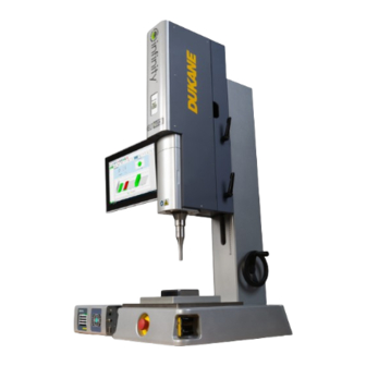
Introduction Press System Overview The Infinity Series Servo Ultrasonic Press System is used for welding thermoplastics. A typical Infinity™ ultrasonic welding system is shipped completely with a press (thruster, base, and column), generator, an ultrasonic stack (transducer, booster, horn), fixturing, cables, and a HMI (with the IQ Explorer 3 software installed) for application setup and data acquisition. -
Page 8: Drawings And Tables
Drawings and Tables The figures and tables are identified by the section number followed by a sequence number. The sequence number begins with one in each section. The figures and tables are numbered separately. Notes, Cautions and Warnings Throughout this Quick Start Guide, CAUTION and WARNING statements are used. These statements help you to identify and avoid hazards and recognize the consequences. -
Page 9: Section 2 - Health And Safety
SECTION Health and Safety 403-618-03 Infinity™ Series Servo Ultrasonic Press Systems User Manual... -
Page 10: General Considerations
Dukane Keep the Cover On - Do not remove any equipment covers unless directed does not assume any responsibility to do so by Dukane. Hazardous electrical voltages are present which could or liability for fixtures manufactured cause injury. - Page 11 Safe Operation CAUTION Parts being joined ultrasonically will at times vibrate at audible frequencies. Wear ear protectors to reduce annoying or uncomfortable sounds. In addition, ultrasound baffles, sound enclosures, or materials that absorb sound may be located to surround the system. Ultrasound pressure level could exceed 90dBA. See TUV test report number 31370614.003 for more detail on specific model numbers and frequencies.
-
Page 12: Electrical Safety
• Infinity™ Generator • Infinity™ Servo Press • Dukane HMI Each of these components must be grounded, including power grounding and RFI suppression grounding. North American Power Grounding For safety, the power cords used with your system have three-wire, grounding-type power cords. Figure 2-1 illustrates the appropriate... -
Page 13: Grounding For Rfi Suppression
This filter also prevents ultrasonic RFI from being fed back into the AC power line. Grounding wires are shipped with each system component (green/yellow; 5 meters long; Dukane part number 200-1557). It is important to connect each of these wires to the nearest grounded metal pipe or equivalent earth ground by means of a ground clamp. -
Page 14: Regulatory Agency Compliance
Regulatory Agency Compliance The Infinity™ generator complies with the following Federal Communications Commission regulations. • The limits for FCC measurement procedure MP-5, “Methods of Measurement of Radio Noise Emissions from ISM Equipment”, pursuant to FCC Title 47 Part 18 for Ultrasonic Equipment. CE Marking This mark on your equipment certifies that it meets the requirements of the EU (European Union) concerning interference causing equipment regulations. -
Page 15: Section 3 - Installation
SECTION Installation 403-618-03 Infinity™ Series Servo Ultrasonic Press Systems User Manual... -
Page 16: Before Installation
Before Installation As you plan for the installation of your system, including generator and press, please consider these important WARNING subjects as listed below: Electrical safety hazards exist inside the • When to use lockout / tagout devices generator, press, and remote controller units . •... -
Page 17: Ac Power Requirements
AC Power Requirements The AC line voltage and current needed depends on which generator and press has been chosen for the system. See Tables 3-1 and 3-2. Generators Overload Input AC Power Requirements North America/ Output Output Power Operating Generator Model Nominal AC Volt at Maximum Japan AC Outlet Voltage... -
Page 18: Dukane Hmi
AC Power Requirements Dukane HMI AC line voltage - 90-260 VAC AC line current - 1 Amp Unpacking the System The system has been assembled and packaged at the factory for shipment. Depending on the system, components may be packaged in multiple crates or boxes. - Page 19 The workbench should be sturdy enough to handle more than the weight of the press system. A sturdy solid workbench is required to prevent the press from unwanted vibratory oscillations. To place the press on the work area, first lift it using the lifting eye bolt shown in Fig. 3-3 below or a pallet lift platform as shown in Fig.
- Page 20 MOUNTING HOLE LOCATIONS (2) EACH SIDE Figure 3-6 Mounting Bolt Holes (X1 Systems Only) UNITS: INCHES [MM] 18.6 [472] ULTRASOUND STACK CENTER 24.84 [630.9] 8.05 [204.3] MOUNTING HOLE .70 [17.8] .50 [12.7] 13.22 [335.8] LOCATIONS Figure 3-7 Mounting Bolt Holes (X2 Systems Only) 403-618-03 Infinity™...
- Page 21 Figure 3-8 X2 System with Round Column Figure 3-9 X2 System with Rigid Column 403-618-03 Infinity™ Series Servo Ultrasonic Press Systems User Manual...
-
Page 22: Cable Connections
2. Connect cable 9 if optional automation equipment is used with the system. 3. Connect power cords 6-8. 4. Arrange cables as desired, but do not bundle the power cords (6-8) with any other cables. Cable Generator Thruster Length Dukane Cable Description Designation Designation (Meters) Part Number Number... -
Page 23: System Inputs/Outputs Signal Pinouts On The J5 Connector
CyCLE START INPUT which cannot be programmed to another function. 2) Inputs and Outputs can be re-programmed via the iQ Commander software. iQ Commander can be downloaded from the following link: https:/ /update.dukane.com 403-618-03 Infinity™ Series Servo Ultrasonic Press Systems User Manual... -
Page 24: System Inputs/Outputs Signal Descriptions On The J5 Connector
System Inputs/Outputs Signal Descriptions on the J5 Connector Application note AN533 provides additional information about automation interface guidelines and can be viewed/downloaded at the https:/ /documents.dukane.com/AppNote/AN533.pdf following link: Pin 1 (+22VDC) This pin can supply +22VDC at up to 500mA to power the user’s automation controls. - Page 25 System Inputs/Outputs Signal Descriptions on the J5 Connector Pin 17 Programmable Output Status J5 Pin 17 (Servo Error) This status output signal will activate only when a servo related error occurs. This output can be re-programmed to Overtemp or Top of Stroke. This output is active for the following alarms: Force Duration Exceeded (U201) Part Detected Too Early by the Servo Controller (U206)
-
Page 26: Section 4 - Tooling Setup
SECTION Tooling Setup 403-618-03 Infinity™ Series Servo Ultrasonic Press Systems User Manual... -
Page 27: Tooling Setup For Model 43Ntx1N
Any fixture manufactured by a third party must comply with all OSHA and ANSI requirements. All fixtures must be guarded as necessary. Dukane does not assume any responsibility or liability for fixtures manufactured by the customer or any third party manufacturer. -
Page 28: Installing The Ultrasonic Stack Module (43Ntx1N)
Installing the Ultrasonic Stack Module 1. Activate the E-STOP (Abort) switch on the front of the press base by pushing it forward as shown in Fig. 4-2. 2. Turn off power to the generator by placing the AC switch in the “0” position. 3. - Page 29 4. Remove the door as shown in Fig. 4-4 and set aside. 5. Completely loosen the (2) booster block screws shown in Fig. 4-5. These screws are captive and will stay with the block. 6. Remove the block as shown in Fig. 4-6 and set aside. 7.
- Page 30 8. Remove the booster clamp plate shown in Fig. 4-8. 9. Insert the ultrasonic stack (transducer, booster, and horn) into the booster block as shown in Fig. 4-9. 10. Insert the booster clamp plate into the booster block as shown in Fig. 4-10. Figure 4-8 Booster Clamp Plate Figure 4-9 Inserting the Ultrasonic Stack Figure 4-10 Inserting the Booster Clamp Plate...
- Page 31 11. Secure the booster clamp plate as shown in Fig. 4-11 with the (4) screws removed earlier. 12. Insert the ultrasonic stack module into the press as shown in Fig. 4-12, aligning the holes in the block with the pins on the press.
- Page 32 14. Place the transducer door onto the press as shown in Fig. 4-14, aligning the holes in the door with the pins on the press. 15. Tighten the transducer door screws shown in Fig. 4-15 until snug, about 1.5 ft/lbs (2 Nm). DO NOT OVER-TIGHTEN! Figure 4-14 Transducer Door Placement Figure 4-15 Tightening the Transducer Door...
-
Page 33: Removing The Ultrasonic Stack Module (43Ntx1N)
Removing the Ultrasonic Stack Module Perform the following steps. The first two steps are necessary to ensure that no power will be accidentally applied while removing the stack. 1. Activate the E-STOP (Abort) switch on the front of the press base by pushing it forward as shown in Fig. 4-16. 2. - Page 34 4. Remove the door as shown in Fig. 4-18 and set aside. 5. Completely loosen the (2) booster block screws indicated in Fig. 4-19. These screws are captive and will stay with the block. 6. Remove the ultrasonic stack module as shown in Fig. 4-20. Figure 4-18 Removing Transducer Door Figure 4-19 Booster Block Screws Figure 4-20 Removing Stack Module...
-
Page 35: Removing The Module Block From The Stack (43Ntx1N)
Removing the Module Block from the Stack 1. Remove the (4) screws from the bottom of the booster block, then remove the booster clamp plate as shown in Fig. 4-21. 2. Remove the booster block by sliding it toward the transducer approximately 1 inch [25 mm], then lifting it up as shown in Fig. -
Page 36: Orienting The Stack/Horn (43Ntx1N)
Orienting the Stack / Horn 1. Loosen the (4) screws securing the transducer door (refer to Fig. 4-17). 2. Loosen the (4) booster clamp screws shown in Fig. 4-23 about 1/4 to 1/2 turn. 3. Rotate the horn to the desired orientation. 4. -
Page 37: Tooling Setup For Model 43Ntx2N
Any fixture manufactured by a third party must comply with all OSHA and ANSI requirements. All fixtures must be guarded as necessary. Dukane does not assume any responsibility or liability for fixtures manufactured by the customer or any third party manufacturer. -
Page 38: Installing The Ultrasonic Stack Module (43Ntx2N)
Installing the Ultrasonic Stack Module 1. Activate the E-STOP (Abort) switch on the front of the press base by pushing it forward as shown in Fig. 4-25. 2. Turn off power to the generator by placing the AC switch in the “0” position. 3. - Page 39 4. Remove the transducer door as shown in Fig. 4-27. 5. With the stack at the angle shown in Figure 4-28, rest the booster mounting ring on the block or pin of the stack housing (highlighted in yellow). 6. Brace the stack at point 1 and swing the stack to a vertical position at point 2 as shown in Figure 4-28. The ultrasound contact button on the transducer should snap under the electrical contact leaf of the housing.
- Page 40 7. While still supporting the stack in this vertical position, install the transducer door as shown in Fig. 4-29, and thread the four socket-head screws (that hold the door closed) into their holes as shown in Fig. 4-30. 8. If the horn is not properly aligned with the fixture, rotate the stack to align the horn with the fixture. 9.
-
Page 41: Removing The Ultrasonic Stack Module (43Ntx2N)
Removing the Ultrasonic Stack Module Perform the following steps. The first two steps are necessary to ensure that no power will be accidentally applied while removing the stack. 1. Activate the E-STOP (Abort) switch on the front of the press base by pushing it forward as shown in Fig. 4-31. 2. - Page 42 4. While supporting the stack with one hand, loosen the four socket-head screws that secure the stack access door. Remove the door as shown in Fig. 4-33 and set aside. 5. Pull the stack forward and down until the transducer clears the electrical contact. Refer to Figure 4-34. Figure 4-33 Removing Transducer Door Figure 4-34 Removing Stack Module 403-618-03 Infinity™...
-
Page 43: Orienting The Stack/Horn (43Ntx2N)
Orienting the Stack / Horn The ultrasonic stack / horn angular orientation is adjusted as follows. 1. Loosen the (4) transducer door screws as shown in Fig. 4-35. 2. Rotate the horn to the desired orientation. 3. Tighten the (4) transducer door screws until snug, about 1.5 ft/lbs (2 Nm). DO NOT OVER-TIGHTEN! Figure 4-35 Loosening Transducer Door Screws 403-618-03 Infinity™... -
Page 44: Tooling Setup For Model 43Ntx3N
Any fixture manufactured by a third party must comply with all OSHA and ANSI requirements. All fixtures must be guarded as necessary. Dukane does not assume any responsibility or liability for fixtures manufactured by the customer or any third party manufacturer. -
Page 45: Installing The Ultrasonic Stack Module (43Ntx3N)
Installing the Ultrasonic Stack Module 1. Activate the E-STOP (Abort) switch on the front of the press base by pushing it forward as shown in Fig. 4-37. 2. Turn off power to the generator by placing the AC switch in the “0” position. 3. - Page 46 5. Unlock the handle shown in Fig. 4-39 by rotating it until it stops. 6. Pull the handle shown in Fig. 4-40 to rotate the transducer clamp open until it stops. 7. Place the ultrasonic stack module into the press by sliding it in as shown in Fig. 4-41. Push it all the way in so that the booster mounting block is inserted onto the pins in the press.
- Page 47 11. The handles must be oriented approximately as shown in Fig. 4-45. Once tightened, the handle orientations can be changed as follows: Pull the handle straight out. b. Turn the handle in either direction as needed. Release the handle to let it spring back into place. 12.
-
Page 48: Removing The Ultrasonic Stack Module (43Ntx3N)
Removing the Ultrasonic Stack Module Perform the following steps. The first two steps are necessary to ensure that no power will be accidentally applied while removing the stack. 1. Activate the E-STOP (Abort) switch on the front of the press base by pushing it forward as shown in Fig. 4-48. 2. - Page 49 Figure 4-50 Unlocking Clamp Figure 4-51 Opening Clamp Figure 4-52 Unlocking Clamp Figure 4-53 Removing Stack Module 403-618-03 Infinity™ Series Servo Ultrasonic Press Systems User Manual...
-
Page 50: Removing The Module Block From The Stack (43Ntx3N)
• Use only the tools recommended by Dukane. NEVER clamp a horn, booster, or transducer in a vise or use tools such as pliers, vise grips, etc. Doing so will result in scratches and/or gouges, resulting in stress areas on the surface. This condition will affect the stack operation and could lead to failure of each stack component. -
Page 51: Orienting The Stack/Horn (43Ntx3N)
Orienting the Stack / Horn 1. Remove the transducer door (refer to Fig. 4-49). 2. Open the transducer clamp (refer to Fig. 4-50 and 4-51). 3. Loosen the (4) booster clamp screws shown in Fig. 4-56 a small amount, such as 1/4 turn. 4. -
Page 52: Tooling Setup For Model 43Ntx4N
Any fixture manufactured by a third party must comply with all OSHA and ANSI requirements. All fixtures must be guarded as necessary. Dukane does not assume any responsibility or liability for fixtures manufactured by the customer or any third party manufacturer. -
Page 53: Installing The Ultrasonic Stack Module (43Ntx4N)
Installing the Ultrasonic Stack Module If the ultrasonic stack module is not installed in the press, follow the instructions below, depending on the model. 1. Activate the E-STOP (Abort) switch on the front of the press base by pushing it forward as shown in Fig. 4-58. 2. - Page 54 5. Remove the 6 mm hex wrench, Dukane part number 809-721-0013, stored on the inside of the door as show in Fig. 4-60, then set the door aside. 6. Use the wrench to loosen the (2) transducer clamp bar screws shown in Fig. 4-61.
- Page 55 8. Place the ultrasonic stack module into the press by sliding it in as shown in Fig. 4-54. Push it all the way in so that the booster mounting block is inserted onto the pins in the press. 9. Tighten the (4) booster clamp screws shown in Fig. 4-55. 10.
-
Page 56: Removing The Ultrasonic Stack Module (43Ntx4N)
Figure 4-70 E-Stop Button (Abort) Figure 4-71 Door Release Button 5. Remove the 6 mm hex wrench, Dukane part number 809-721-0013, stored on the inside of the door as shown in Fig. 4-72, then set the door aside. 6. Use the wrench to loosen the (2) transducer clamp bar screws as shown in Fig. 4-73. - Page 57 Figure 4-72 Hex Wrench Storage Location Figure 4-73 Removing Transducer Clamp Bar Figure 4-74 Rotating Transducer Clamp Bar Figure 4-75 Clamp Resting Position 403-618-03 Infinity™ Series Servo Ultrasonic Press Systems User Manual...
-
Page 58: Removing The Module Block From The Stack (43Ntx4N)
• Use only the tools recommended by Dukane. NEVER clamp a horn, booster, or transducer in a vise or use tools such as pliers, vise grips, etc. Doing so will result in scratches and/or gouges, resulting in stress areas on the surface. This condition will affect the stack operation and could lead to failure of each stack component. -
Page 59: Orienting The Stack/Horn (43Ntx4N)
Orienting the Stack / Horn The ultrasonic stack/horn angular orientation is adjusted as follows, depending on the model. 1. Remove the transducer door (refer to Fig. 4-71). 2. Loosen the transducer clamp bar screws (refer to Fig. 4-72 and 4-73). 3. -
Page 60: Adjusting The Thruster Position (For X1, X3 And X4)
Adjusting the Thruster Position (for X1, X3 and X4) Adjusting the Thruster Position 1. Before unlocking the handles, hold the adjustment wheel tightly to prevent it from rotating. Unlock all the handles (2 or 3, depending on the model) shown in Fig. 4-79 below by turning them counter-clockwise until they stop (approximately 1/2 turn). - Page 61 3. A scale is provided on the column as shown in Fig. 4-81 to indicate the thruster position. 4. Lock all the handles tightly by turning them clockwise as shown in Fig. 4-82. 5. If desired, the orientation of the handles can be changed once they are locked. Referring to Fig. 4-83, pull the handle straight out (1), rotate it in either direction (2), then release it (3).
-
Page 62: Adjusting The Thruster Position (For X2)
Adjusting the Thruster Position (for X2) Adjusting the Thruster Position 1. Before unlocking the handles, hold the adjustment wheel tightly to prevent it from rotating. Loosen the handles shown in Fig. 4-84 below by turning them counter-clockwise. Tightening the handles by turning them clockwise. Figure 4-84 Loosening and Tightening Lock Handles 403-618-03 Infinity™... - Page 63 2. Turn the crank wheel clockwise to raise the thruster, or counter-clockwise to lower as shown in Fig. 4-85. 3. Lock all the handles tightly by turning them clockwise. 4. If desired, the orientation of the handles can be changed once they are locked. Referring to Fig. 4-86, pull the handle straight out (1), rotate it in either direction (2), then release it (3).
-
Page 64: Aligning The Fixture (For All Models)
Aligning the Fixture (for all models) The fixture must be properly aligned and leveled to the horn to ensure consistent, evenly distributed welds. To safely align the fixture under the horn, use the following procedure. 1. Place unwelded parts into the fixture. 2. -
Page 65: Section 5 - Controls And Indicators
SECTION Controls and Indicators 403-618-03 Infinity™ Series Servo Ultrasonic Press Systems User Manual... -
Page 66: Control And Indicators Overview
Controls and Indicators Control and Indicators Overview This section contains information about the visual indicators, manual switches and adjustments of the components in a typical IQ Infinity™ system. The press, generator, and HMI will be discussed. Press System Figure 5-1 shows the controls and indicators for the press, generator, and HMI. THRUSTER COLUMN GENERATOR... -
Page 67: Press Controls And Display
Press Controls and Display THRUSTER POWER SWITCH THRUSTER DISPLAY INDICATOR (NOT PRESENT IN ALL MODELS) COLUMN LOCK HANDLES THRUSTER HEIGHT ADJUSTMENT WHEEL HORN FIXTURE E-STOP OPERATING / SAFETY SWITCHES Figure 5-2 Press Controls and Display 403-618-03 Infinity™ Series Servo Ultrasonic Press Systems User Manual... -
Page 68: Operating Safety Switch Detail
Operating / Safety Switch Detail ACTIVATION AREA STATUS LED GREEN POWER LED Figure 5-3 Operating Safety Switch E-Stop Switch Detail PUSH TO ACTIVATE TWIST CLOCKWISE TO RELEASE Figure 5-4 E-Stop (ABORT) Switch 403-618-03 Infinity™ Series Servo Ultrasonic Press Systems User Manual... -
Page 69: Hmi Connections
HMI Connections AC POWER CONNECTION ETHERNET PORTS HMI POWER SWITCH Figure 5-5 HMI Connections 403-618-03 Infinity™ Series Servo Ultrasonic Press Systems User Manual... -
Page 70: Section 6 - Operation
SECTION Operation 403-618-03 Infinity™ Series Servo Ultrasonic Press Systems User Manual... -
Page 71: Iq Explorer 3 Overview
Operation IQ Explorer 3 Overview The IQ Explorer 3 software comes standard on a Dukane HMI. This program connects with the Infinity™ generator/press through a user interface and is used for configuration and setup. Key Features IQ Explorer 3 User Interface •... -
Page 72: Getting Started Using Iq Explorer 3
Getting Started Using IQ Explorer 3 STEP 1 - Getting Started Ensure that a proper connection of the IQ Explorer 3 software and the servo press has been made. See Figure 6-1 below. Name of the connected welder. Names of active welders in the network appear when Show Welders tab is clicked. - Page 73 STEP 3 - Cycle Initiate Settings Click on the Process Settings tab. Select Manual from the pull down menu as shown in Figure 6-3. Manual - The Manual cycle initiate mode requires two push buttons (safety switch 1 and 2) to be pressed within 350 milliseconds of each other.
- Page 74 Application note AN506 provides additional information about the Trigger by Power™ feature and can be viewed/ https:/ /documents.dukane.com/AppNote/AN506.pdf downloaded at: Position - The trigger source is via the distance encoder. When the position is reached the ultrasound signal is triggered.
- Page 75 STEP 5 - Program the Sensing Speed The Sensing Speed is the speed (inches/millimeters per second) at which the horn will move during the approach just before reaching the trigger position. A typical starting value for Sensing Speed is 1.0 mm/s (0.040 in/s). The Sensing Speed can be set higher for shorter cycle times, or lower for greater trigger force detection accuracy.
- Page 76 Enable Melt-Detect™ This patented feature is found only on Dukane's servo press systems. If the feature is enabled, as shown in Figure 6-7, the system will stop motion once the desired Trigger Force is achieved. The ultrasound will be initiated at this moment. Once the programmed Melt-Detect™...
- Page 77 Primary Method On the Process Settings tab, find Weld > Primary Method, and select Distance. Distance - This is the distance the welder advances once the programmed trigger force is reached. Usually this distance is the height of the energy director, or shear joint of the part being welded. Max Time is a component of the weld method intended to offer a measure of safety.
- Page 78 STEP 11 - Post Weld Settings The post weld phase of the process is sometimes overlooked; however, it is important in achieving desired weld results. The Infinity™ servo welder has several exclusive post weld control parameters that can improve weld bond strength and process repeatability.
- Page 79 Static Hold Method The press motion stops for a specified amount of time to allow for molten plastic to solidify. This phase is called static hold. To program static hold, set the Static Hold Method to Time, and enter the desired Hold Time. Once the static hold phase is complete, the press retracts back to the Top-of-Stroke position.
- Page 80 Process Limits Force at Sensing Start Position - This is the force value detected by the load cell at the Sensing Start Position. If the sensing start position is set properly high enough above the part, typically 0.5-1.0 mm (0.020-0.040 in), the force value there will be typically below 50 N (11 lbs).
- Page 81 Free Run Frequency significantly reduces the chances that an alarm will occur during start up. Application note AN512 provides additional information about the Scan Stack feature and can be viewed/downloaded at https:/ /documents.dukane.com/AppNote/AN512.pdf the following link: Figure 6-14 Stack Scan 403-618-03 Infinity™...
- Page 82 STEP 14 - Testing the Ultrasonic Stack After performing the Scan Stack feature, press and hold the TEST button on the front panel of the generator. The operational parameters displayed are Amplitude, Frequency, and Power. Changing any of the stack component (transducer, booster, or horn) will result in different frequency and power values.
-
Page 83: Section 7 - Specifications
SECTION Specifications 403-618-03 Infinity™ Series Servo Ultrasonic Press Systems User Manual... -
Page 84: Thruster Specifications
Thruster Specifications Maximum Linear Encoder Maximum Horn Stroke Maximum Speed Weld Force Resolution Weight Thruster Model in/s mm/s 43NTX1N 0.00004 43NTX1S 13.8 0.00004 43NTX2N 2450 0.00004 11.4 43NTX3N 2450 0.00004 11.4 43NTX4N 1000 4450 0.00004 27.3 Table 7-1 Thruster Specifications Operating Environment Operate the equipment within these guidelines: Temperature: 40°F to 100°F (+5°C to +38°C) -
Page 85: Model Outline Drawings
Model Outline Drawings Layout drawings and 3D models can be obtained on the Dukane "Drawings and Layouts" web page at the link below: https:/ /support.dukane.com/layouts/Index/Ultrasonic Welding Model Number Description Drawing Number _ _ _ _._y.C_-X1_._R Infinity™ X1 System 400-2720 _ _ _ _._y.C_-X1_._LR Infinity™... -
Page 86: Infinity™ Generator Number Guide
403-618-03 Infinity™ Series Servo Ultrasonic Press Systems User Manual... -
Page 87: Infinity™ System Number Guide
403-618-03 Infinity™ Series Servo Ultrasonic Press Systems User Manual... -
Page 88: Section 8 - Alarm Messages
SECTION Alarm Messages 403-618-03 Infinity™ Series Servo Ultrasonic Press Systems User Manual... -
Page 89: Alarm Messages
The following lists of alarms, on pages 80-83, that may appear on the servo press systems containing a generator with a color front panel display and/or IQ Explorer 3 software. Information on particular alarms may also be obtained on the Dukane '"Easy Alarm" web page at the link below: https:/ /support.dukane.com/EasyAlarm... - Page 90 There is a problem with the Valve Safety Cycle power on the generator and/or press/thruster. Fault Equipment installed inside the press. If alarm persists, contact Dukane. U116 Ultrasound Voltage The actual transducer voltage exceeded the The stack operating frequency is too far away from the...
- Page 91 Adjust weld parameters to reduce the distance traveled during the weld and hold. U213 Servo Communication Communication between the servo control- Contact Dukane. Error ler and the motherboard has been compro- mised. U214 Obstruction at Top of The press is unable to reach the Top-of- Remove obstruction detected at Top of Stroke.
- Page 92 Wait for initialization process to complete. Ready Cycle power on iQ/AiM/Infinity generator. The Automation Cycle Stop input may be activated. If alarm persists, contact Dukane. U400 Weld Limits enabled for Weld Limits enabled for continuous Change Weld Mode from Automation.
- Page 93 Alarm Code Alarm Message Explanation Solution U414 Max Trigger Delay Time Trigger delay distance was not reached Increase maximum trigger delay time. Exceeded within the specified time limit. Start the weld process sooner. U415 Max Trigger Delay Time The max trigger delay time is set to 0. Adjust the maximum trigger delay time to be greater Set to Zero than 0.
-
Page 94: Section 9 - Maintenance
SECTION Maintenance 403-618-03 Infinity™ Series Servo Ultrasonic Press Systems User Manual... -
Page 95: System Maintenance
Disconnect t remove the thruster left and right side covers. 2. Check if any fasteners are visibly loose. If so, contact Dukane for the proper tightening torque. 3. Wipe or blow away all dirt and grease in the thruster. 4. No air is required for the normal operation of a servo press. However, there may be a time when optional cooling accessories were added. -
Page 96: Contacting Dukane
Contacting Dukane Identify Equipment When contacting Dukane about a service–related problem, be prepared to give the following information: • Model number, line voltage and serial number. • Alarm/Fault indicators from the display. Software version (Press INFO. With selection indicators at System Information, press ENTER to get this data). -
Page 97: Dukane Iso Certification
Dukane chose to become ISO certified in order to demonstrate to our customers our continuing commitment to being a quality vendor. By passing its audit, Dukane can assure you that we have in place a well–defined and systematic approach to quality design, manufacturing, delivery and service. This certificate reinforces Dukane’s status as a quality vendor of technology and products. -
Page 98: Contacting Dukane
Please refer to our website at: www.dukane.com/contact-us to locate your local representative. 403-618-03 Infinity™ Series Servo Ultrasonic Press Systems User Manual...
Need help?
Do you have a question about the Infinity Series and is the answer not in the manual?
Questions and answers