
Related Manuals for Anritsu CMA50


Summary of Contents for Anritsu CMA50
- Page 1 CMA50 Operation Manual Eighth Edition For safety and warning information, please read this manual before attempting to use the equipment. Keep this manual with the equipment. ANRITSU CORPORATION Part No.: 41315I...
- Page 2 26 June 2006 (First Edition) 6 July 2010 (Eighth Edition) ©2006 - 2010 ANRITSU CORPORATION All rights reserved. No part of this manual may be reproduced without the prior written permission of the publisher. The contents of this manual may be changed without prior notice.
-
Page 3: Safety Symbols
Ensure that you clearly understand the meanings of the symbols BEFORE using the equipment. Some or all of the following symbols may be used on all Anritsu equipment. In addition, there may be other labels attached to products that are not shown in the diagrams in this manual. - Page 4 CMA50 Operation Manual Safety Symbols Used on Equipment and in Manual The following safety symbols are used inside or on the equipment near operation locations to provide information about safety items and operation precautions. Ensure that you clearly understand the meanings of the symbols and take the necessary precautions BEFORE using the equipment.
-
Page 5: For Safety
For Safety DANGER NEVER touch parts where the label shown on the left is attached. Such parts have high voltages of at least 1kV and there is a risk of receiving a fatal electric shock. WARNING ALWAYS refer to the Operation Manual when working near locations at which the alert mark shown on the left is attached. If the advice in the Operation Manual is not followed there is a risk of personal injury or reduced equipment performance. - Page 6 CMA50 Operation Manual IEC 61010 Standard The IEC 61010 standard specifies four categories to ensure that an instrument is used only at locations where it is safe to make measurements. This instrument is designed for measurement category I (CAT I). DO NOT use this instrument at locations specified as category II, III, or IV as defined below.
- Page 7 To reduce risk of equipment damage, injury, or death, adhere to the following warnings: Shock • Do not use the CMA50 or its AC charger/adapter if the case of either is cracked or damaged. • Use the CMA50 only with the AC charger/adapter provided for the CMA50 by Anritsu. Anritsu does not guarantee the safety and functionality of other power supplies.
- Page 8 The performance-guarantee seal verifies the integrity of the equipment. To ensure the continued integrity of the equipment, only Anritsu service personnel, or service personnel of an Anritsu sales representative, should break this seal to repair or calibrate the equipment. If the performance-guarantee seal is broken by you or a third party, the performance of the equipment cannot be guaranteed.
- Page 9 Replacing Battery When replacing the battery, use the specified battery and insert it with the correct polarity. If the wrong battery is used, or if the battery is inserted with reversed polarity, there is a risk of explosion causing severe injury or death.
- Page 10 CMA50 Operation Manual Battery Fluid DO NOT short the battery terminals and never attempt to disassemble the battery or dispose of it in a fire. If the battery is damaged by any of these actions, the battery fluid may leak. This fluid is poisonous.
- Page 11 Laser Safety Class 1, 1M, and 2 indicate the danger degree of the laser radiation specified below according to IEC 60825-1:2007. Class 1: Lasers that are safe under reasonably foreseeable conditions of operation, including the use of optical instruments for intrabeam viewing.
- Page 12 CMA50 Operation Manual WARNING The laser in this equipment is classified as Class 1 or 3R according to the IEC 60825-1:2007 standard. Table 1 Laser Safety Classifications Based on IEC 60825-1:2007 Max. Optical Pulse Width (s)/ Emitted Laser Beam Diver-...
- Page 13 Table 1 Laser Safety Classifications Based on IEC 60825-1:2007 (Continued) Max. Optical Pulse Width (s)/ Emitted Laser Beam Diver- Output Power Product Type Model Name Class Repetition Rate Wavelength Aperture gence (deg) (mW)* (nm) 1310 nm 11.5 Fig. 1 [2] 50LTS 3456/ 1490 nm 11.5...
- Page 14 CMA50 Operation Manual Table 2 Incorporated Laser Specification Type Model Name Max. Optical Pulse Width (s)/ Emitted Wavelength Beam Divergence Output Power Repetition Rate (nm) (deg) (mW)* 1.41 1310 11.5 50LTS35/ 50LS 35 1.41 1550 11.5 1.41 1310 11.5 50LTS345/ Loss Test Set (LTS)/ 1.41...
- Page 15 Table 2 Incorporated Laser Specification (Continued) Type Model Name Max. Optical Pulse Width (s)/ Emitted Wavelength Beam Divergence Output Power Repetition Rate (nm) (deg) (mW)* 1.41 1310 11.5 50LTS 3456/ 1.41 1490 11.5 50LS 3456 1.41 1550 11.5 1.41 1625 11.5 Loss Test Set (LTS)/ Light Source (LS...
- Page 16 CMA50 Operation Manual Table 3 Indication Labels on Product Type Sample Affixed to: Model Name 50LTS35/ 1 Certification Fig. 1, A 50LS35/ 50LTS345/ 50LS345/ 50LTS356/ 2 Class 1 Laser Fig. 1, B 50LS356/ 50LTS3456/ 50LS3456/ 50LTS8335/ 3 Identification Fig. 1, C...
- Page 17 Table 3 Indication Labels on Product (Continued) Type Sample Affixed to: Model Name 4 Class 3R Laser Fig. 1, D 50-OPT-V 5 Warning Fig. 1, E 6 Aperture Fig. 1, F xvii...
- Page 18 CMA50 Operation Manual xviii Laser Radiation Markings [3] [2] Fig. 1: Location of Laser Beam Apertures and Affixed Labels...
- Page 19 Leave the product on until the power indicator goes off; the battery is now discharged. Remove the battery. Deliver it to your local recycling center, or mail it to the following address: ANRITSU COMPANY 490 Jarvis Drive Morgan Hill, CA 95037-2809...
- Page 20 CMA50 Operation Manual For EU & EFTA Customers Please Recycle Read the following when using products to which the marks shown to the left are attached. The product that you have purchased contains a rechargeable battery. The battery is recyclable. At the end of its useful life, under various state and local laws, it may be illegal to dispose of this battery into the municipal waste.
- Page 21 In addition, this warranty is valid only for the original equipment purchaser. It is not transferable if the equipment is resold. Anritsu Corporation shall assume no liability for injury or financial loss of the customer due to the use of or a failure to be able to use this equipment.
- Page 22 Anritsu Corporation Contact In the event that this equipment malfunctions, contact an Anritsu Service and Sales office. Contact information can be found on the last page of the printed version of this manual, and is available in a separate file on the CD version.
- Page 23 Copying files and data Only files that have been provided directly from Anritsu or generated using Anritsu equipment should be copied to the instrument. All other required files should be transferred by means of USB or CompactFlash media after undergoing a thorough virus check.
- Page 24 Equipment marked with the Crossed-out Wheeled Bin Symbol complies with council directive 2002/96/EC (the “WEEE Directive”) in the European Union. For products placed on the EU market after August 13, 2005, please contact your local Anritsu representative at the end of the product’s useful life to arrange disposal in accordance with your initial contract and the local law.
- Page 25 CE Conformity Marking Anritsu affixes the CE conformity marking on the following product(s) in accordance with the Council Directive 93/68/EEC to indicate that they conform to the EMC and LVD directive of the European Union (EU). CE marking 1. Product Model...
- Page 26 CMA50 Operation Manual xxvi LVD: Directive 2006/95/EC 3. Applied Standards • EMC Emission: EN61326-1: 2006 (Class A) Immunity: EN61326-1: 2006 (Table 2) Performance Criteria* IEC 61000-4-2 (ESD) IEC 61000-4-3 (EMF) IEC 61000-4-4 (Burst) IEC 61000-4-5 (Surge) IEC 61000-4-6 (CRF) IEC 61000-4-11 (V dip/short)
- Page 27 • LVD: EN 61010-1: 2001 (Pollution Degree 2) • Laser Safety: EN60825-1 Part 1 4. Authorized Representative Name: Murray Coleman Head of Customer Service EMEA ANRITSU EMEA Ltd. Address, City: 200 Capability Green, Luton Bedfordshire, LU1 3LU Country: United Kingdom xxvii...
- Page 28 CMA50 Operation Manual xxviii C-Tick Conformity Marking Anritsu affixes the C-Tick mark on the following product(s) in accordance with the regulation to indicate that they conform to the EMC framework of Australia/New Zealand. C-Tick marking 1. Product Model Model: CMA50 Loss Test set 2.
- Page 29 The following notices are applicable to China RoHS Requirements only. xxix...
- Page 30 CMA50 Operation Manual...
- Page 31 xxxi...
- Page 32 Technical Support Center for instructions. Whether or not the warranty period of your Anritsu product has expired, the unit can be returned to Anritsu for repairs. Out-of-warranty repairs are billed for time and materials. Call our Technical Support Center for further information.
-
Page 33: Table Of Contents
Light Source Connection ..........1-16 Hybrid Universal Connector and Adapters ...1-16 For Safety ..............v Cleaning the Hybrid Universal Connector .....1-18 Chapter 1: CMA50 Series Overview ....... 1-1 Cleaning Hybrid Universal Adapters .....1-19 Theory of Operation ............1-2 Changing the Hybrid Universal Adapter ....1-19 Unpacking and Inspection .......... - Page 34 No Save Mode ............2-4 Select Wavelengths Menu ..........2-19 VFL Mode ............... 2-4 Mass Storage Menu ............2-21 CMA50 Operating Mode Selection Guide ..... 2-5 Save File ...............2-22 Measurement Mode LCD Layout ........2-6 Close File ..............2-24 Main Measurement Display – Power Meter & Loss Test Name File .............2-25...
- Page 35 More (access to Setups Menu screen 2) ....2-47 Remote Reference Input .........3-6 Modulation Freq (Frequency) ....... 2-48 Optical Loss Measurements ..........3-7 Auto Shut Down ............ 2-50 Patch Panel to Patch Panel Test Method ....3-7 Software Upgrade ..........2-51 Patch Panel to Connector Test Method ....3-9 Backlight ...............
- Page 36 First Time 10/100 Ethernet Connection (Direct peer to Troubleshooting and Messages ........5-8 peer connection) ........... 4-19 Recommended Calibration ..........5-9 Normal Ethernet Operation ........4-24 Appendix A: CMA50 Series Specifications ... A-1 Data File Download ............. 4-27 Index ................. IX-1 Software Upgrade Procedures ........4-28...
-
Page 37: Chapter 1: Cma50 Series Overview
Chapter 1: CMA50 Series Overview The CMA50 series consists of Power Meters, Light Sources and Loss Test Sets, all of which are light-weight, yet rugged in design to handle any testing situation. Designed for attenuation and throughput measurements of fiber optic links, the CMA50 Power Meters are ideal for troubleshooting networks. -
Page 38: Theory Of Operation
Theory of Operation The interchangeable connector adapter system couples light from the fiber under test to the CMA50’s receiver, a high performance InGaAs photodetector that converts the light energy to an electrical signal. The CMA50 then digitizes the signal for processing by a microcontroller. -
Page 39: Unit Description
Unit Description Front Panel The front panel of each CMA50 unit includes the following components: LED Indicators for future applications LCD Display A backlit graphic LCD displays measurement results, test parameters, ➀ etc. ➁ Keypad Sealed elastomeric keypad provides simple operation and environmental ➂... -
Page 40: Top Panel
CMA50 Operation Manual Top Panel Depending on the configuration of the unit, the CMA50 top panel includes the following components: 1 Power Meter This port, labeled POWER METER, couples the fiber under test to the optical power port meter via an interchangeable connector adapter. -
Page 41: Back Panel
Back Panel The back panel of each CMA50 unit includes the following components: Serial Number Serial number of the unit, in numeric and bar code forms. label ➀ Model Number Model number of the unit. ➁ label (includes source wavelengths for Light Sources and Loss Test Sets only) ➂... -
Page 42: Bottom Panel
CMA50 Operation Manual Bottom Panel The CMA50 bottom panel includes the following components: 1 10/100 The port, identified by this symbol , allows support of basic ethernet Ethernet port functions (such as PING testing, on units equipped with the Network Test option) and software upgrades. - Page 43 This port, labeled “7.5VDC 2A”, accepts the AC charger/adapter for external AC powering and re-charging of the Ni-MH input battery pack. 5 I/O port door The I/O port door protects the various connectors when they are not in use. Fig. 1-5 on page 1-6 shows the door in its open position. Chapter 1: CMA50 Series Overview...
-
Page 44: Keypad
Note The CMA50 can be forced to power down in any situation by holding down the Power key for more than 30 seconds, forcing the unit to reset. - Page 45 The function of this softkey varies. The current function of the softkey is as indicated by its designator in the lower right corner of the LCD display. Note Note The Right softkey is referred to as the “Auto Test” key on older (i.e.: NetTest branded) CMA50 units. Chapter 1: CMA50 Series Overview...
- Page 46 CMA50 Operation Manual 1-10 TX (Transmit) – Up Arrow Key • Power Meter Mode/Optical Return Loss Mode: This key has no function in Power Meter mode and Optical Return Loss mode. • Loss Test Set Mode: The TX – Up Arrow key toggles the transmitter (Light Source or VFL) ON and OFF.
- Page 47 Pressing the dBm/W – Right Arrow key will traverse (if applicable) and highlight any selections in the right direction. Note Note The legend on the dBm/W key is “UNITS” on older (i.e.: NetTest branded) CMA50 units. 1-11 Chapter 1: CMA50 Series Overview...
- Page 48 CMA50 Operation Manual 1-12 λ (Wavelength) – Left Arrow Key • Power Meter Mode: Press the λ – Left Arrow key to cycle through all of the selected factory calibrated wavelengths. The LCD displays the measured power (in dBm) for the applicable wavelengths.
- Page 49 Select or clear a selection (as indicated by placing or removing a check mark in front of the selected item). Move the highlight to an editable field. Note Note The legend on the FUNCTION key is “ENTER” on older (i.e.: NetTest branded) CMA50 units. 1-13 Chapter 1: CMA50 Series Overview...
-
Page 50: Power Meter Connection
CMA50 Operation Manual 1-14 Power Meter Connection Power Meter Adapter Caps LP-D4 LP-LC LP-FC LP-ST D4 Adapter LC Adapter FC Adapter ST Adapter LP-SC LP-DIN LP-U125 LP-UN Universal SC Adapter DIN Adapter 1.25mm Adapter 2.5mm Adapter... -
Page 51: Cleaning The Power Meter Port
Other Power Meter adapter caps are available. Contact Anritsu for details. Cleaning the Power Meter Port The Power Meter port on the CMA50 should be cleaned if you can see contaminant. It is not necessary to perform this procedure with each use. Remove the adapter cap (if in place). -
Page 52: Light Source Connection
Hybrid Universal Connector and Adapters Depending on the configuration of your CMA50 it may be equipped with one or two Hybrid Universal connectors (multimode/singlemode Quad wavelength Loss Test Sets and Light Sources are equipped with two). The Hybrid Universal connector’s dust cap protects the ferrule’s tip from dust, dirt, or damage which could affect measurement results. - Page 53 Adapter Adapter In addition to the adapters pictured above, Hybrid Universal adapter are also available for DIN (UNIV-DIN) and LC (UNIV-LC) style connectors. Other hybrid universal adapters may be available. Contact Anritsu for details. Note Note The UNIV-SC can be used with both UPC-SC and APC-SC style connectors.
-
Page 54: Cleaning The Hybrid Universal Connector
Wipe the ferrule tip clean with a precision cleaning tissue moistened with isopropyl alcohol. Apply compressed air to dry the ferrule tip. OPTIONAL: With the CMA50 powered down, inspect the ferrule using a hand microscope or magnifier. It should appear similar to the Clean Ferrule tip in Fig. 1-7. -
Page 55: Cleaning Hybrid Universal Adapters
To change the dust cap: Use a small Phillips screwdriver to remove the screw that attaches the dust cap chain to the top plate of the CMA50. Retain the screw. Use the screw removed in step 1 to attach the chain of the new dust cap to the top plate of the CMA50. -
Page 56: Connecting Fiber To The Source Port
CMA50 Operation Manual 1-20 Connecting Fiber to the Source Port Clean and connect a patch cord of known good quality to the hybrid universal adapter attached to the Source port. Clean the connector of the system to be tested. Attach the free end of the patch cord to the connector of the system to be tested. -
Page 57: Cautions On Handling Optical Fiber Cables
Doing so may break the optical fiber inside the cable. Keep the bend radius of an optical fiber cable at 30 mm or more. If the radius is less, optical fiber cable loss will increase. 1-21 Chapter 1: CMA50 Series Overview... - Page 58 CMA50 Operation Manual 1-22 CAUTION Do not excessively pull on or twist an optical fiber cable. Also, do not hang anything by using a cable. Doing so may break the optical fiber inside the cable. CAUTION Be careful not to hit the end of an optical connector against anything hard such as the floor or a desk by dropping the optical fiber cable.
- Page 59 Do not touch the end of a broken optical fiber cable. The broken optical fiber may pierce the skin, causing injury. CAUTION Do not disassemble optical connectors. Doing so may cause part to break or the performance to degrade. 1-23 Chapter 1: CMA50 Series Overview...
- Page 60 CMA50 Operation Manual 1-24...
-
Page 61: Chapter 2: Getting Started
Bi-directional option). Additionally, units equipped with the Visual Fault Locator (VFL) option can operate in VFL mode. EZ Test mode, LTS mode and PM mode can automatically save measurement readings to the CMA50’s internal data storage as both PMT and TXT files. -
Page 62: Ez Test Mode - Automated Bi-Directional Loss Testing
EZ Test Mode – Automated Bi-Directional Loss Testing The EZ Test mode automated bi-directional loss test is an optional feature available for CMA50 Loss Test Sets. Using two similar CMA50 LTS units, (compatible source/meter wavelengths) the EZ Test mode performs automated bi-directional loss measurements on a fiber link. The two units act as a “Master”... -
Page 63: Power Meter Mode
Optical Return Loss Mode Optical Return Loss (ORL) mode is an optional feature for CMA50 singlemode Loss Test Sets that are equipped with the Automatic Bi-directional Test option. ORL mode utilizes a Wizard to establish the critical Incident Power and a Mandrel Wrap reference value in order to provide accurate ORL measurement values. -
Page 64: No Save Mode
CMA50 Operation Manual No Save Mode No Save mode allows you to make Power Meter or Loss Test Set measurements in a non-storage mode of operation. Mass Storage is not supported in No Save mode. VFL Mode Visual Fault Locator (VFL) mode is available on units equipped with the VFL option. See “Visual Fault Locate Mode” on page 3-42 for details. -
Page 65: Cma50 Operating Mode Selection Guide
CMA50 Operating Mode Selection Guide Measure Units Measure Power Independent Save Data GN6025 Mode Link Loss Wavelengths Automation Required dBm or dBr Light Source to File Compatible EZ Test All installed singlemode Full, Always (Master/Slave) laser sources Bi-Directional EZ Test 6025... -
Page 66: Measurement Mode Lcd Layout
CMA50 Operation Manual Measurement Mode LCD Layout Note Note The unit defaults to the wavelength, power units, and reference power level (if applicable) displayed during the last operation of unit. Main Measurement Display – Power Meter & Loss Test Set Modes Source Mode Indicates whether the light source is ON or OFF. - Page 67 Filename Filename for the current test data. Fiber Count Number assigned to the current fiber under test. Power Units dBm or Watts for absolute power; dBr for relative power. Right Softkey Displays the current function assigned to the right softkey. Reference Value Displays the reference power level in dBm when the unit is in relative power mode (dBr).
-
Page 68: Main Measurement Display - No Save Mode
CMA50 Operation Manual Main Measurement Display – No Save Mode Fig. 2-2 depicts a typical measurement in No Save mode. Note Note This screen displays the same indicators as detailed in Fig. 2-1, except that it does not display a filename, fiber count or the right and left softkey indicators. -
Page 69: Main Measurement Display - Ez Test Mode
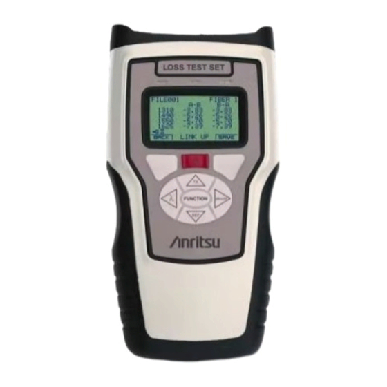
Main Measurement Display – EZ Test Mode Filename File name for the current test data. Test Wavelengths Wavelengths selected for the current test A-B Measurement Measurement results (in dB) for the current test in the A-B Results direction per each wavelength tested. B-A Measurement Measurement results (in dB) for the current test in the B-A Results... -
Page 70: Main Measurement Display - Ez Test 6025 (Auto Wave Id) Mode
CMA50 Operation Manual 2-10 Plug Icon or Indicates that the unit is connected to an external power supply (plug icon– see Fig. 2-3) or the unit is operating on battery Battery Icon power (battery icon) with the amount of remaining charge displayed. - Page 71 Plug Icon or Indicates that the unit is connected to an external power supply (plug icon– see Fig. 2-4) or the unit is operating on battery Battery Icon power (battery icon) with the amount of remaining charge displayed. Fig. 2-5 depicts a typical EZ Test 6025 (Auto Wave ID) mode receiver display. Upon entry, the unit defaults to receiver mode. Press the TX key to switch the unit to transmitter mode.
- Page 72 CMA50 Operation Manual 2-12 Reference Value Displays the reference power level in dBm when the unit is in relative power mode (dBr). Note Note A reference value is only displayed when a reference is set. See “Setting References” on page 3-1 for more information) Left Softkey Labeled as either “A B”...
-
Page 73: Main Measurement Display - Optical Return Loss Mode
Main Measurement Display – Optical Return Loss Mode Filename Filename for the current test data. Fiber Count Number assigned to the current fiber under test. Wavelength List List of the available wavelengths. Up to four wavelengths may be displayed. The current operating wavelength is highlighted and is followed by the current ORL measurement, in dB, at that wavelength. -
Page 74: Light Source Display
See “Auto Shut Down” on page 2-50 for more information. Light Source Display The display for a Light Source only CMA50 is shown in Fig. 2-7. The unit defaults to the wavelength and modulation mode displayed at last operation of unit. -
Page 75: Vfl Display
VFL Display Units equipped with the VFL (Visual Fault Locator) option display the screen shown in Fig. 2-8 when VFL is selected as the operating mode. See “VFL Testing” on page 3-42 for additional information. Indicates that the unit is currently set to VFL mode. Source ON/OFF Indicates whether the VFL source is: ON (transmitting in CW mode), 2H (modulated transmission at 2Hz) or OFF. -
Page 76: Menus And Screen Functions
Depending on the configuration of the CMA50 in use and the operating mode selected, not all menu items may be available. Selecting a menu item which is not available for the unit and/or operating mode causes the CMA50 to display a warning screen. - Page 77 The MENU softkey is only available on the Mode Select screen right after power up – until you run a test. After running a test, the softkey legend changes to BACK. Note Note Operating mode selection does not apply to CMA50 Light Sources that do not have the VFL option. Chapter 2: Getting Started 2-17...
-
Page 78: File Save Mode
CMA50 Operation Manual 2-18 File Save Mode Use the File Save mode screen to set the save environment when testing in either Power Meter (PM) mode or Loss Test Set (LTS) mode. To set the File Save mode: Select either PM or LTS on the Mode Select screen (see Fig. 2-10). The File Save mode screen (Fig. -
Page 79: Select Wavelengths Menu
SELECT WAVELENGTHS and then press the FUNCTION key. The Select Wavelengths screen appears. Note The number of wavelengths varies with the type of the CMA50 unit Fig. 2-12: Select Wavelengths Screen with Default (Power Meter/Loss Test Set/Light Source) and its current Operating mode Selections (EZ Test, Loss Test Set, Power Meter, or Optical Return Loss mode). - Page 80 Loss Test Set Mode/Optical Return Loss Mode/EZ Test Modes– Only the wavelengths that support the on-board Light Sources are displayed on Select Wavelength screen. For example, a Quad singlemode CMA50 Loss Test Set would display the following wavelengths; 1310nm, 1490nm, 1550nm, and 1625nm.
-
Page 81: Mass Storage Menu
• • Save File Load File • • Close File Delete File(s) • • Name File Erase Drive • Storage Mode Note Note The Mass Storage menu functions are not available on CMA50 Light Sources. Chapter 2: Getting Started 2-21... -
Page 82: Save File
CMA50 Operation Manual 2-22 Save File Measurement data may be saved to a file at any time. This operation saves all measurements taken up to performing the save. Once the SAVE is performed, the file is still open and active when you return to the measurement mode screen and store more readings. - Page 83 WARNING If a file already exists with the same name, the warning message, shown in Fig. 2-15 appears. Select the SAVE softkey to overwrite the file or select the CNCL (Cancel) softkey and then select FILE NAME from the Mass Storage menu to set up a new name for the file.
-
Page 84: Close File
CMA50 Operation Manual 2-24 Close File The CLOSE FILE function allows you to save all the measurements taken up to this point and closes the file to any further measurement data. Once a CLOSE is performed, the current file is closed and a new file is opened for the collection of new measurements. -
Page 85: Name File
Name File Select NAME FILE to set up a filename and enable or disable the filename auto-incrementing option. By default the filename field contains the last saved filename, or the next number increment filename when the filename auto-increment feature is enabled. Filenames cannot exceed eight characters. - Page 86 CMA50 Operation Manual 2-26 Note Use the BKSP softkey to delete characters/digits from the File Name field. When you have finished editing the filename, press the FUNCTION key. The initial File Name screen appears with the new file name displayed.
-
Page 87: Storage Mode
Storage Mode The STORAGE MODE menu item allows you to select the current operating mode’s auto-incrementing behavior as well as entering a Fiber Count start value. Note Note Storage Mode selection does not apply when operating either the Power Meter or Loss Test Set in a No Save mode;... - Page 88 CMA50 Operation Manual 2-28 To set the Storage Mode: With the Mass Storage menu displayed (see Fig. 2-13 on page 2-21) highlight STORAGE MODE and then press the FUNCTION key. The Storage Modes screen appears. Highlight the desired storage mode by using the Up and Down Arrow keys and then press the FUNCTION key to select it. The selected mode displays a check mark to its left.
-
Page 89: Load File
Load File The LOAD FILE menu item allows you to load a saved file for viewing or editing. The type of file which can be loaded depends on the current operating mode. Power Meter files can only be loaded when in either Power Meter mode or LTS mode, while ORL files can only be loaded in ORL mode. - Page 90 CMA50 Operation Manual 2-30 To edit a file: Make sure that the proper test setup is established. See Chapter 3, “Test Methods” for details on the various test setups. Follow the steps outlined in “To load a file” on page 2-29 if you do not currently have a saved file loaded.
- Page 91 Note When editing an ORL file a prompt screen is displayed which allows you to establish new values for the Incident power and Mandrel reference (see Fig. 2-26). See steps 7 through 11 on pages 3-36 through 3-38 for details and then proceed to step 6 below.
- Page 92 CMA50 Operation Manual 2-32 10. Press the DONE softkey. The Save Changes to File screen appears (see Fig. 2-27): • Press the YES softkey to save the file with the changes made and return to the Load File screen (see Fig. 2-21 on page 2-29).
-
Page 93: Delete File(S)
Delete File(s) The DELETE FILE(S) menu item presents a list of filenames through which you can scroll and select an archived file, or group of files, for deletion. To delete files: With the Mass Storage menu displayed (see Fig. 2-13 on page 2-21) highlight DELETE FILE(S) and then press the FUNCTION key. -
Page 94: Erase Drive
2-34 Erase Drive The ERASE DRIVE menu item allows a user to erase all data files saved to the CMA50’s FLASH drive. To erase the FLASH drive: With the Mass Storage menu displayed (see Fig. 2-13 on page 2-21) highlight ERASE DRIVE and then press the FUNCTION key. The Erase Drive screen appears. -
Page 95: Communications
The COMMUNICATIONS menu item provides access to setup the CMA50 for functions including: retrieval of data (readings) stored on the unit, supporting basic ethernet functions (such as Ping testing), and remote operation, via the unit’s USB and 10/100 Ethernet ports. See Fig. 1-5: “CMA50 Unit Bottom”on page 1-6 for location of the ports. -
Page 96: Network Testing
CMA50 Operation Manual 2-36 Network Testing The NETWORK TESTING menu item provides access to the PING test function. See “PING Test” on page 3-43 for details. Note Note You cannot select the NETWORK TESTING menu item until you have selected 10/100 Ethernet on the Communications Port screen (see... -
Page 97: Setups Menu
Setups Menu The Setups menu provides access to the various Setups selections. The Setups menu is divided over two screens. To access the Setups Menu screen 1: With the Main Menu displayed (see Fig. 2-9 on page 2-16) highlight SETUPS and then press the FUNCTION key. Screen 1 of the Setups Menu appears. -
Page 98: Display Resolution
Note The Display Resolution setting does not apply to CMA50 Light Source only units or to test results in EZ Test mode. EZ Test mode automatically uses the 2 place decimal reading. ORL mode also only uses the 2 place decimal reading. -
Page 99: Set Thresholds
Set Thresholds The SET THRESHOLDS menu item allows you to set values that trigger the PASS/FAIL indicator (see Fig. 2-1 on page 2-6). Thresholds can be set either manually or via a wizard. In addition, the ORL threshold settings are also accessed through the Set Thresholds mode screen. - Page 100 10. Repeat steps 4 through 9 until all desired threshold values are entered. 11. Press the BACK softkey to return to the Setups Menu screen 2. Note Note Set Thresholds does not apply to CMA50 Light Source only units. Fig. 2-34: Set Thresholds Screen – Manual...
- Page 101 Thresholds Wizard Setup The Thresholds Wizard provides a means to calculate the thresholds, at all wavelengths, based on expected network loss. With the Setups menu displayed (see Fig. 2-32 on page 2-37) highlight SET THRESHOLDS and then press the FUNCTION key. The Set Thresholds mode screen appears (see Fig.
- Page 102 CMA50 Operation Manual 2-42 Press the NEXT softkey, the Fiber Specs screen appears (see Fig. 2-36). Use the Up/Down/Right/Left Arrow keys to enter the desired values (see Step 4 on page 2-41 for details) for the fiber under test for the following:...
- Page 103 ORL Thresholds Setup The ORL thresholds setting is accessed through the Set Thresholds mode screen (see Fig. 2-33 on page 2-39). With the Setups menu displayed (see Fig. 2-32 on page 2-37) highlight SET THRESHOLDS and then press the FUNCTION key. The Set Thresholds mode screen appears.
-
Page 104: Lcd Contrast
Note The user-set contrast setting is maintained by the CMA50 on a power cycle. The contrast setting is also maintained when the unit is reset to its factory defaults via the FACTORY DEFAULTS menu item (see “Factory Defaults” on page 2-45). -
Page 105: Factory Defaults
The FACTORY DEFAULTS menu item provides a way to return the various Setups menu items to their factory default settings. To set the CMA50 to its factory defaults: With the Setups menu displayed (see Fig. 2-32 on page 2-37) highlight FACTORY DEFAULTS and then press the FUNCTION key. The Set Defaults screen appears. -
Page 106: Speaker (On/Off)
Speaker (ON/OFF) The SPEAKER setting is an ON or OFF item which instructs the CMA50 (Loss Test Sets only) to sound a tone at the end of an EZ Test. If set to ON, the tone sounds at the end of an EZ Test, or to indicate an interruption in the test. In addition, when the Speaker is set to ON, a tone sounds in Power Meter or Loss Test Set mode when a signal, modulated at the same frequency set in the Modulation Frequency setting (see “Modulation Freq... -
Page 107: More (Access To Setups Menu Screen 2)
More (access to Setups Menu screen 2) The MORE menu selection provides access to the Setups Menu screen 2. To access the Setups Menu screen 2: With the Setups Menu screen 1 displayed, (see Fig. 2-32 on page 2-37) highlight MORE and then press the FUNCTION key. Screen 2 of the Setups Menu appears. -
Page 108: Modulation Freq (Frequency)
Modulation Freq (Frequency) The MODULATION FREQ feature allows selection of a modulated frequency on CMA50 Power Meters and Loss Test Sets. The selected modulation frequency defines the source output frequency, as well as the detection frequency for display. This feature is primarily used as a method of fiber identification. - Page 109 In addition, if a Modulated signal is detected when operating in either Power Meter or Loss Test Set mode, with FILE SAVE enabled, the SAVE softkey and REF hardkey will be disabled. To set the Modulation Frequency: With the Setups Menu screen 1 displayed (see Fig. 2-32 on page 2-37), highlight MORE and then press the FUNCTION key.
-
Page 110: Auto Shut Down
2-50 Auto Shut Down AUTO SHUT DOWN automatically powers down the CMA50 after a set time based on instrument keypad and USB or 10/100 Ethernet inactivity. The Auto Shut Down interval can be set from 1 through 99 minutes. Its default setting is 10 minutes. -
Page 111: Software Upgrade
Note Subsequent presses of FUNCTION key will toggle the highlight between MIN and the previously highlighted digit. Press the BACK softkey to return to screen 2 of the Setups Menu. Software Upgrade See “Software Upgrade Procedures” on page 4-28 for details. Backlight The BACKLIGHT setting allows you to set the duration that the display backlight is turned on after a keypress. - Page 112 CMA50 Operation Manual 2-52 To set the Backlight: With the Setups Menu screen 1 displayed (see Fig. 2-32 on page 2-37), highlight MORE and then press the FUNCTION key. Screen 2 of the Setups Menu appears. Highlight BACKLIGHT and then press the FUNCTION key. The Backlight screen appears (see Fig. 2-44 on page 2-51).
-
Page 113: Language
Language Use the Language setting to select the operating language for the unit. To set the Language: With the Setups Menu screen 1 displayed (see Fig. 2-32 on page 2-37), highlight MORE and then press the FUNCTION key. Screen 2 of the Setups Menu appears. -
Page 114: Auto Zero
Note If the message “AUTO ZERO FAILED” appears, make sure that the detector (Power Meter port) is completely blocked, and then perform the Auto Zero again. If the procedure fails again, contact the Anritsu Technical Support Center (see page xxxii). -
Page 115: Version Information
Press the INFO softkey. The Version Information screen appears. Note Note Fig. 2-47 is provided as a visual reference only. The model, serial number, and software version dates will vary depending on the given CMA50 unit. Chapter 2: Getting Started 2-55... - Page 116 CMA50 Operation Manual 2-56 To view the Version Information screen while in a test mode: Press the FUNCTION key when in the Measurement Results screen for the current test. The Main Menu screen appears (see Fig. 2-9 on page 2-16).
-
Page 117: Chapter 3: Test Methods
Note Note For best results when setting references, set the operating mode of the CMA50 to a No Save mode. This allows you to cycle through the wavelengths via the λ (Wavelength) key. Use the following procedure to set a reference value for the current wavelength. -
Page 118: Manual Reference Setting
CMA50 Operation Manual Manual Reference Setting To set a manual reference, use the λ (Wavelength) key to cycle to the desired wavelength. Press the REF key, the Reference screen appears (see Fig. 3-1 on page 3-1). Make sure that REFERENCE is highlighted. -
Page 119: Verifying Patchcords
Press the SAVE softkey to save the reference value. The meter returns to the Measurement display which indicates 0.0 dBr (relative loss). Reverse the connections. If the loss displayed on the CMA50 (Meter) is ≤0.5dB, the patchcord is good and will provide a valid test. Otherwise, clean the connectors or, if necessary, replace the patchcord and repeat steps 4 and 5 until a reading of ≤0.5dB or less is achieved. -
Page 120: Absolute Power
LOSS TEST SET equipment using the fiber under test. Set the CMA50 so that the power unit is set to dBm by pressing the dBm/W key until the power units on the display reads “dBm” (see Fig. 2-1 on page 2-6). -
Page 121: System Attenuation (Loss) Measurements
Press the REF key on the CMA50 meter. The Reference screen appears (see Fig. 3-1 on page 3-1). Press the SAVE softkey. The meter returns to the Measurement display which indicates 0.0 dBr (relative loss). -
Page 122: Remote Reference Input
Remote Reference Input As an alternative to the Local Reference method, two CMA50 Loss Test Sets can be referenced remotely. The two users can go directly to opposite ends of the system without the need to reference together at a common site. To perform system testing in this manner, substitute the following Manual Reference procedure for the Local Reference Input method (see page 3-5). -
Page 123: Optical Loss Measurements
Optical Loss Measurements This section details three different testing scenarios: • Patch Panel to Patch Panel Test Method • Patch Panel to Connector Test Method • Connector to Connector Test Method Patch Panel to Patch Panel Test Method Patch Panel to Patch Panel is the most commonly used test method. This procedure requires two patchcords. LOSS TEST SET LOSS TEST SET Source... - Page 124 Use a second test patchcord to connect the CMA50 acting as the meter to the opposite end of the system to be tested. Power readings will be in dB and include two connector pairs and loss across the fiber.
-
Page 125: Patch Panel To Connector Test Method
Patch Panel to Connector Test Method This procedure requires two patchcords and an in-line adapter. LOSS TEST SET LOSS TEST SET Source Meter FUNCTION dBm/W FUNCTION dBm/W Fig. 3-7: Patch Panel to Connector Depending on your test setup, establish the reference, using either: “Local Reference Input”... - Page 126 Leave the patchcords connected at both the CMA50 acting as the meter and the CMA50 acting as the source, using an in-line adapter attached to the patchcord that will be attached at the connector end of the fiber under test.
-
Page 127: Connector To Connector Test Method
Connector to Connector Test Method This procedure requires three patchcords and two in-line adapters. LOSS TEST SET LOSS TEST SET Source Meter FUNCTION dBm/W FUNCTION dBm/W Fig. 3-8: Connector to Connector Depending on your test setup, establish the reference, using either: “Local Reference Input”... - Page 128 3-12 Remove the second patchcord after the source, leaving the in-line adapters attached to the patchcords connected to the CMA50 acting as the meter and the CMA50 acting as the source. Leave the patchcords connected to the meter and source in place.
-
Page 129: Editing Power Measurement Readings
Editing Power Measurement Readings Use the following procedure to edit saved power measurement readings. Press the EDIT softkey on the Main Measurement Display screen (see Fig. 3-9). The Browse screen (see Fig. 3-10 on page 3-14) appears with the Fiber Count number highlighted. Note The EDIT softkey is only available when operating in either Power Meter Mode or Loss Test Set Mode. - Page 130 CMA50 Operation Manual 3-14 Use the Up/Down Arrow keys to cycle through the Fiber Count number. If you cycle to a Fiber Count number for which there is no power measurement value, the screen appears as shown in Fig. 3-10.
-
Page 131: Ez Test Mode
Physical Connection EZ Test mode requires two CMA50 units, one to act as the Master and one to act as the Slave. See Fig. 3-12. Fiber Under Test... -
Page 132: Auto Bi-Directional Loss Measurement
CMA50 Operation Manual 3-16 Auto Bi-Directional Loss Measurement Power up both units and then select EZ TEST on the Mode Select screen (see Fig. 2-10 on page 2-17). The EZ Test Mode screen appears. Fig. 3-13: EZ Test Mode Screen On one unit, highlight MASTER and then press the FUNCTION key. - Page 133 Fig. 3-14: EZ Test Setup Screen Use this screen to select the wavelengths and type of referencing used for the test. Navigate the screen by using the Right, Left, Up, and Down Arrow keys to place the highlight in the desired position. •...
- Page 134 CMA50 Operation Manual 3-18 • To change the reference type: Move the highlight to the desired type of reference. The reference types are listed in the right hand column of the EZ Test Setup screen. Press the FUNCTION key to select the highlighted reference type. A Wizard for the selected reference type is launched.
- Page 135 Note The legend at the bottom of the screen changes from “LINKING” to “LINK UP” when the link is established. Fig. 3-17: Initial EZ Test Results Screen - Linking Fig. 3-18: EZ Test Results Screen - Bi-directional Upon completion of the test, the bi-directional loss data (in dB units) for the current fiber is presented in the “A-B” and “B-A” columns. Use the λ...
- Page 136 CMA50 Operation Manual 3-20 Fig. 3-19: EZ Test Results Screen - Two Way Averaged Note Results that exceed the Threshold settings (see “Set Thresholds” on page 2-39) will be highlighted on the EZ Test Results screen. Press the SAVE softkey on both units. The measurement data is saved to Mass Storage and the units prompt for the connection of the next fiber.
-
Page 137: Setting References In Ez Test Mode
Fig. 3-20: Select Next Fiber Screen Fig. 3-21: Please Wait for Next Fiber Number Screen Setting References in EZ Test Mode There are three methods of setting references for an auto bi-directional loss test in EZ Test mode: Side by Side, Loopback, and Manual. All three are accessed from the EZ Test Setup screen (see Fig. - Page 138 Connect the two patch cords together using the inline adapter and then connect the free ends of the patchcords to the SM (singlemode) ports on the CMA50 LTS units, as shown in the figure above. Press the NEXT softkey on both units. The Master unit attempts to establish a link to the Slave unit, as indicated by the message “LINKING”...
- Page 139 Note If communications cannot be established after several attempts, the text message displays “NO LINK”, this indicates a bad patchcord. Replace the patchcord and retry. Fig. 3-24: Taking References – Link Up Fig. 3-23: Taking References – Linking Once the communication link is established, the first selected wavelength is highlighted and the reference power value is posted on the display. Each wavelength in turn is highlighted and the applicable reference is displayed.
- Page 140 CMA50 Operation Manual 3-24 Note Do not disconnect the patchcord end connected to the source after referencing. The coupled output level of the source may change when the patchcord is reconnected. Fig. 3-25: References Save Screen Loopback Reference The Loopback reference method requires two short patchcords (3 meters or less), one for each unit (Master and Slave). This method is useful when the two units (Master and Slave) are at different locations.
- Page 141 Highlight LOOPBCK on the EZ Test Setup screen (see Fig. 3-14 on page 3-17) and then press the FUNCTION key. The initial Loopback wizard screen appears (see Fig. 3-26). Use one of the patchcords to connect the Power Meter port to the SM (singlemode) port on the Master unit. Using the other patchcord, repeat on the Slave unit.
- Page 142 CMA50 Operation Manual 3-26 When reference values for all test wavelengths are established, the References Saved screen appears (see Fig. 3-25 on page 3-24). Continue the bi-directional measurement by pressing the TEST softkey on both units or press the BACK softkey to return to the initial Loopback wizard screen to reestablish the reference values if they are not acceptable.
- Page 143 Manual Reference Manual referencing allows editing of the current reference values, and also provides a means of clearing all currently displayed reference values. Follow steps 1 through 4 of the “Auto Bi-Directional Loss Measurement” procedure on page 3-16. Highlight MANUAL on the EZ Test Setup screen (see Fig. 3-14 on page 3-17) and then press the FUNCTION key. The Manual Reference wizard screen appears.
- Page 144 CMA50 Operation Manual 3-28 Press the FUNCTION key. The highlight moves to the last digit of the reference value for the selected wavelength. If there was no reference for the wavelength, the text “NONE” changes to “-00.00”, with the highlight on the last “0”.
-
Page 145: Ez Test 6025 (Auto Wavelength Id) Mode
Physical Connection 6025 (Auto Wave ID) mode requires two CMA50 units, one to act as the transmitter (light source) and one to act as the receiver (power meter). See Fig. 3-30. Fiber 1: A... -
Page 146: Setting References In 6025 (Auto Wave Id) Mode
CMA50 Operation Manual 3-30 Setting References in 6025 (Auto Wave ID) Mode References for 6025 (Auto Wave ID mode testing are set in the same manner as references in standard Power Meter mode. See “Setting and Clearing Reference Readings” on pages 3-1 through 3-2 for details. - Page 147 Attach the CMA50 receiver (meter) unit to the other end of the fiber under test. Press the TX key on the CMA50 transmitter unit. The display should be similar to the one shown in Fig. 3-33 on page 3-32. Chapter 3: Test Methods...
- Page 148 CMA50 Operation Manual 3-32 Fig. 3-33: 6025 Mode – Transmitter Display The current wavelength is highlighted and followed by the TX indicator. The unit will continually cycle through the selected wavelengths. The unit acting as the receiver displays the currently detected wavelength, followed by the measured power level. The wavelength and power...
- Page 149 10. To advance to the next fiber, save the current measurement. This will cause the unit to advance to the next Fiber Count. Measurement files can be loaded on to the CMA50 for viewing and editing. See “Load File” and “Editing a File” on pages 2-29 through 2-31 for details.
-
Page 150: Optical Return Loss Mode
Standard ORL test for the first time ORL test when using a new unit, or for the first test after upgrading the unit’s applications software. ORL mode requires a CMA50 Loss Test Set equipped with both Option B (EZ Test) and Option O (ORL). - Page 151 Select the desired test wavelengths by pressing the Left Arrow key. The ORL Wavelength Selection screen appears (see Fig. 3-36 on page 3-35) with the first wavelength highlighted. If the desired wavelengths are already selected, proceed to step 6 Fig. 3-36: ORL Wavelength Selection Screen Fig.
- Page 152 CMA50 Operation Manual 3-36 Press the TEST softkey, the Incident Power setup diagram screen appears (see Fig. 3-37). Attach a patchcord between the Power Meter port and the SM (singlemode) port, as shown in the diagram. Note Make sure that the end of the patchcord connected to the SM (singlemode) port has an angle-polished connector.
- Page 153 Fig. 3-39. Do not disturb the connection at the SM (singlemode) port. 10. Wrap the patchcord around the mandrel (provided with the CMA50 ORL Loss Test Set), typically 6 to 8 wraps (see Fig. 3-40). Fig. 3-40: Mandrel Wrap Chapter 3: Test Methods...
- Page 154 CMA50 Operation Manual 3-38 11. Press the NEXT softkey, the Mandrel Reference collection begins for the selected wavelengths. The reading at each selected wavelength is rated as either GOOD, FAIR, or POOR. Reading for each wavelength updates at about one second intervals. When you achieve the desired readings (either FAIR or GOOD at all selected wavelengths), press the SAVE softkey to stop collection (see Fig.
- Page 155 Note To correct a POOR mandrel reference, make one or two additional wraps of the patchcord around the mandrel. If that fails to clear the POOR readings; press the CNCL softkey and then press the BACK softkey to return to the initial screen of the ORL Reference wizard (see Fig. 3-35 on page 3-34), clean the connection at the SM (singlemode) port and then press the TEST softkey to repeat the Incident Power reference and the Mandrel reference (start at Step 7 on page 3-36).
- Page 156 CMA50 Operation Manual 3-40 Note The SAVE softkey is not available until ORL readings are displayed for all selected wavelengths 13. Connect the patchcord to the next fiber to be tested and then press the SAVE softkey to continue. The Fiber Count increments to the next number.
-
Page 157: Quick Orl Test
Option O (ORL).” starting on page 3-34. Power up the CMA50 Loss Test Set, select ORL on the Mode Select screen (see Fig. 2-10 on page 2-17) and then press the FUNCTION key. The first screen of the ORL Reference wizard appears (see Fig. 3-35 on page 3-34). -
Page 158: Visual Fault Locate Mode
Visual Fault Locate Mode Visual Fault Locate (VFL) mode is available on CMA50 units equipped with the Visual Fault Locator option. Connecting a fiber to the Visual Fault Locator (VFL) allows the unit to find breaks or severe bends in the fiber. The VFL produces a visible red glow at the break or bend. -
Page 159: Ping Test
Press the TX key to start the VFL. Press the TX key once to activate CW (continuous wave) mode. Press and hold the TX key for two (2) seconds to switch to the Modulated mode (2Hz). Press the TX key again to turn off the VFL. PING Test The PING test is accessed by selecting NETWORK TESTING on the Main Menu screen (see Fig. - Page 160 CMA50 Operation Manual 3-44 Fig. 3-44: PING Test Screen Edit the IP address, if necessary. Press the FUNCTION key. The highlight moves to the first digit of the IP address. Use the Up/Down Arrow keys to increment/decrement the digit. Use the Left/Right Arrow keys to move the highlight to the next desired digit.
-
Page 161: Chapter 4: Network Connections
USB Drive The USB Drive feature allows Power Meter and ORL files to be transferred from the CMA50 to a PC using a standard USB drive interface. In addition, this feature also provides an simplified method for installing software upgrades. -
Page 162: Accessing The Usb Drive
CMA50 Operation Manual Accessing the USB Drive Access to the USB drive is obtained when the unit is connected to the PC via the “A to mini-B” USB cable. The cable is supplied as part of the CMA50 Communications Accessory Kit. - Page 163 Fig. 4-2: Removable Disk Window Chapter 4: Network Connections...
- Page 164 Main Menu screen (see Fig. 2-9 on page 2-16). OR – If you have just powered ON the CMA50, wait until the Mode Select screen appears (see Fig. 2-10 on page 2-17) and then press the MENU softkey to access the Main Menu screen.
-
Page 165: Usb (Tcp/Ip) Connection
First Time USB (TCP/IP) Connection Note Note A USB connection between the CMA50 and a PC requires a “A to mini-B” cable. This cable is supplied as part of the CMA50 Communications Accessory Kit. On the CMA50 Connect the “mini-B” end of the USB cable to USB port at the base of the CMA50 (see Fig. 1-5 on page 1-6). - Page 166 CMA50 Operation Manual Fig. 4-3: Network Settings Screen If the NETWORK SETTINGS (IP address, MASK, and GATEWAY) are correct, proceed to step 10. In most cases the default settings are sufficient. To change the Network Settings: Use the Up and Down Arrow keys to highlight the desired heading (IP, MASK, or GATEWAY).
- Page 167 10. Press the SET softkey, the Please Wait screen appears, and then the Communications Ports screen appears, with a check mark in front of the USB (TCP/IP) menu item. The current IP address is also displayed. 11. Press the BACK softkey, the Main Menu screen appears, (see Fig. 2-1 on page 2-6). On the PC Place the software CD from the Communications Accessory Kit in the PC’s CD drive.
- Page 168 CMA50 Operation Manual Click the Next> button, a warning message appears (see Fig. 4-5). Fig. 4-5: Hardware Installation Warning Message. Click the Continue Anyway button, the next Wizard screen appears (see Fig. 4-6 on page 4-9).
- Page 169 Fig. 4-6: Found New Hardware Wizard – Completed Click the Finish button. The Wizard finishes the driver installation. Re-boot the PC if prompted by Windows. From the Windows Desktop Right click on My Network Places and then select Properties from the menu. Chapter 4: Network Connections...
- Page 170 CMA50 Operation Manual 4-10 Right click on the Local Area Connection for the USB Ethernet/RNDIS Gadget (Local Area Connection 2 in Fig. 4-7, below). Fig. 4-7: Network Connections Window – USB Ethernet/RNDIS Gadget Selected...
- Page 171 Select Properties from the menu, the Local Area Connection Properties dialog appears (see Fig. 4-8, below). Fig. 4-8: Local Area Connection 2 Properties Dialog Chapter 4: Network Connections 4-11...
- Page 172 CMA50 Operation Manual 4-12 10. Select Internet Protocol (TCP/IP) from the list. Scroll down the list, if necessary. 11. Click the Properties button, the Internet Protocol (TCP/IP) Properties dialog appears (see Fig. 4-9, below). Fig. 4-9: Internet Protocol (TCP/IP) Properties Dialog...
- Page 173 12. Select Use the following IP address. 13. Enter an IP address that is compatible (on the same network) as the address specified on the CMA50. If the default address (192.168.0.2) was used on the CMA50, then 192.168.0.1 is recommended on the PC.
- Page 174 CMA50 Operation Manual 4-14 Fig. 4-10: Broswer with ftp Address...
-
Page 175: Normal Usb (Tcp/Ip) Operation
Connect the “A” end of the USB cable to the PC. If the CMA50 is currently in a measurement mode, continue with the measurement until you reach the Results screen for the test; then press the FUNCTION key on the CMA50. When the Main Menu screen appears (see Fig. 2-9 on page 2-16) continue at step 4 OR –... -
Page 176: 10/100 Ethernet Connection
Connect the remaining end of the Ethernet cable to the LAN port. If the CMA50 is currently in a measurement mode, continue with the measurement until you reach the Results screen for the test; then press the FUNCTION key on the CMA50. When the Main Menu screen appears (see Fig. 2-9 on page 2-16) continue at step 4 OR –... - Page 177 Fig. 4-11: Set IP, Mask, Gateway Screen Press the Up/Down Arrow keys to highlight the DHCP (AUTO) line. Press the FUNCTION key. The PLEASE WAIT message appears while the CMA50 is requesting an IP address from the LAN. Chapter 4: Network Connections...
-
Page 178: Test The Network Connection
CMA50 Operation Manual 4-18 If an IP address is successfully obtained, the NETWORK SETTINGS screen will be displayed and the IP, MASK, and GATEWAY fields will be automatically filled in. Note Take note of the IP address, as it is needed later (see “On the PC” on page 4-18). -
Page 179: First Time 10/100 Ethernet Connection (Direct Peer To Peer Connection)
On the CMA50 Connect one end of the Ethernet crossover cable to 10/100 Ethernet port at the base of the CMA50 (see Fig. 1-5 on page 1-6). Connect the remaining end of the Ethernet crossover cable to the 10/100 Ethernet port on the PC. - Page 180 Note If a peer-to-peer network is used (CMA50 directly connected to a PC), it is customary to use the 192.168.x.x address range. To change the Network Settings: Use the Up and Down Arrow keys to highlight the desired heading (IP, MASK, or GATEWAY).
- Page 181 Fig. 4-12: Network Connection Window – 10/100 Ethernet Device Selected Chapter 4: Network Connections 4-21...
- Page 182 CMA50 Operation Manual 4-22 Select Properties from the menu, the Local Area Connection Properties dialog appears (see, Fig. 4-13 below). Fig. 4-13: Local Area Connection 2 Properties Dialog...
- Page 183 Select Internet Protocol (TCP/IP) from the list. Scroll down the list, if necessary. Click the Properties button, the Internet Protocol (TCP/IP) Properties dialog appears (see Fig. 4-14, below). Fig. 4-14: Internet Protocol (TCP/IP) Properties Dialog Chapter 4: Network Connections 4-23...
-
Page 184: Normal Ethernet Operation
Select Use the following IP address. Enter an IP address that is compatible (on the same network) as the address specified on the CMA50. If the default address (192.168.0.2) was used on the CMA50, then 192.168.0.1 is recommended on the PC. - Page 185 On the CMA50 Connect one end of the Ethernet crossover cable to 10/100 Ethernet port at the base of the CMA50 (see Fig. 1-5 on page 1-6). Connect the remaining end of the Ethernet crossover cable to the 10/100 Ethernet port on the PC.
- Page 186 Open your web browser (Internet Explorer, for example) and enter ftp://192.168.0.2 in the Address line, and then press the Enter key. See Fig. 4-10 on page 4-14. Note If a different IP address was specified on the CMA50, then substitute that address for the address in the bullet above.
-
Page 187: Data File Download
Data File Download Use the following procedure to download data files from the CMA50 to a PC. Establish a Network Connection using one of the methods detailed in the following sections: • USB Drive – see “USB Drive” on page 4-1 •... -
Page 188: Software Upgrade Procedures
IMPORTANT – Copy (backup) all data files from the CMA50 prior to starting the Software Upgrade process (see “Data File Download” on page 4-27). The internal storage will be FORMATTED and ALL FILES WILL BE DESTROYED after the Operating System upgrade is complete. - Page 189 Open your web browser (Internet Explorer, for example) and establish the ftp connection. See “On the PC” on page 4-16 for details. Right click on the web browser window and select Paste from the menu. The selected files are copied from the PC to the CMA50.
- Page 190 9. If the unit does not power off, completely remove power by disconnecting the AC charger/adapter or removing the batteries. If repeated attempts at upgrade are not successful, contact the Anritsu Technical Support Center (see page xxxii).
-
Page 191: Application Upgrade
Open your web browser (Internet Explorer, for example) and establish the ftp connection. See “On the PC” on page 4-16 for details. Right click on the web browser window and select Paste from the menu. The selected files are copied from the PC to the CMA50. - Page 192 CMA50 Operation Manual 4-32 On the CMA50 Press the FUNCTION key, the Main Menu screen appears (see Fig. 2-9 on page 2-16). Press the Up/Down Arrow keys to highlight SETUPS. Press the FUNCTION key, the SETUPS menu (screen 1) appears (see Fig. 2-32 on page 2-37).
- Page 193 Note Note If the SOFTWARE UPGRADE function is requested when a valid set of files is not present on the CMA50’s internal storage, the Update Not Found screen appears (see Fig. 4-18). Fig. 4-17: Update In Progress Screen UPGRADE APP SW...
-
Page 194: Version Verification
CMA50 Operation Manual 4-34 Version Verification See “Version Information” on page 2-55 for details on verifying version information before or after an upgrade. -
Page 195: Chapter 5: Maintenance And Service
Chapter 5: Maintenance and Service Cleaning the CMA50 All surfaces of the CMA50 casework, except for the LCD display, should be cleaned with a soft, lint-free cloth dampened with water. CAUTION Do not use acetone or hydrocarbon cleaners. Doing so may permanently damage the CMA50 and may void your warranty. -
Page 196: Power And Batteries
Only use Ni-MH battery packs supplied by Anritsu. • Replaceable batteries: In absence of either the AC charger/adapter or the rechargeable Ni-MH battery pack, the CMA50 can be powered using 4 AA alkaline batteries. Installing the Ni-MH battery pack... - Page 197 Your unit will require the battery pack WITH insulating plate, if the battery contacts have smaller protrusions as shown below: Your unit will require the battery pack WITHOUT insulating plate, if the battery contacts have larger protrusions as shown below: Chapter 5: Maintenance and Service...
- Page 198 Use the following procedure to install the Ni-MH battery pack. If operating, power down the CMA50. Open the battery compartment, located on the lower back side of the unit, by pulling down on the latch while lifting up on the battery compartment cover.
- Page 199 Slide the Ni-MH battery pack into the battery compartment, making sure that the THIS SIDE UP label is visible. Replace the battery compartment cover. Chapter 5: Maintenance and Service...
-
Page 200: Ac Charger/Adapter
CMA50 Operation Manual WARNING Always turn off the CMA50 before removing either the Ni-MH battery pack or old AA alkaline batteries. If the batteries are removed with the power on, reference values and data files could be lost. Note Note See pages 1-6 and 1-7 for information regarding recharge status of the Ni-MH battery pack. -
Page 201: Battery Replacement - Ni-Mh Battery Pack To Aa Alkaline
CAUTION Do not store the CMA50 for long periods of time with the replaceable alkaline batteries in the unit. The batteries may corrode and/or leak and damage the unit. Chapter 5: Maintenance and Service... -
Page 202: Troubleshooting And Messages
Troubleshooting and Messages Each time the CMA50 is powered up, it performs an internal self-test. The LCD screen displays the Anritsu logo and a progress bar during the self-test. When the self-test is complete, the LCD displays the Mode Selection screen. The unit performs other self-diagnostics and displays the following error... -
Page 203: Recommended Calibration
Recommended Calibration Anritsu recommends that CMA50 units be calibrated once every three (3) years with traceability to a national standard. Many government, military, and quality standards require documentation that equipment has been calibrated within the recommended period. To send a unit in for calibration, see “Technical Support Center”... - Page 204 CMA50 Operation Manual 5-10...
-
Page 205: Appendix A: Cma50 Series Specifications
Appendix A: CMA50 Series Specifications All specifications are subject to change without notice. General Family Specifications Power 4 - AA Alkaline Batteries or Rechargeable NiMH battery pack, 110/220Vac Adapter Battery Life 20 hours, typical Auto Shut-Off Programmable (1 to 99 minutes) or disabled... - Page 206 CMA50 Operation Manual Light Sources Multimode Center Wavelength 850nm 1300nm Wavelength Accuracy ±20nm +30/-20nm Emitter Type Output Power (62.5/125 µm fiber) -20dBm -20dBm Source Linewidth (FWHM) <50nm <200nm Stability (1 hour) ±0.1dB ±0.1dB Output Modes CW (Continuous Wave), 270Hz, 1KHz, 2KHz Modulation...
- Page 207 -75dBm to +10dBm -50dBm to +27dBm 3,4,7 Measurement Accuracy ±0.2dB with P = -65dBm to +5dBm ±0.2dB with P = -37dBm to +27dBm Linearity ±0.1dB ±0.1dB Maximum Input Power +10dBm +27dBm Modulation Detection 270Hz, 1KHz, and 2KHz Appendix A: CMA50 Series Specifications...
- Page 208 CMA50 Operation Manual Power Meters (continued) Wavelength Detection Automatic recognition of calibrated wavelengths (when used in conjunction with a CMA50 light source) Display Resolution 0.01 (mW, µW, nW, dBr, dBm) Auto Bi-Direction Test Mode (Option B) Wavelengths All Equipped Singlemode Wavelengths...
- Page 209 At time of calibration. Calibration conditions: 1310nm, -10dBm, +23°C. Accuracy derates below 1000nm. At 850nm, Measurement Accuracy is ±0.35 with = -60dBm to +5dBm (or P = -32dBm to +27dBm for CATV Option C units). Appendix A: CMA50 Series Specifications...
- Page 210 CMA50 Operation Manual At +23°C, from -65dBm to +2dBm (or -37dBm to +23dBm for CATV Option C units). Do not exceed maximum input power. If the power meter is routinely used to measure optical signals in excess of 0dBm (+20dBm for Option C), more frequent calibration is recommended to insure measurement accuracy.
- Page 211 CMA50 Loss Test Sets (Include Light Source and Power Meter) 50LTS35 50LTS83 50LTS345 50LTS356 50LTS3456 50LTS8335 CMA50 Power Meters 50PMS Standard 50PMC CATV CMA50 Loss Test Set are equipped with either a Standard or CATV (Option C) Power Meter Appendix A: CMA50 Series Specifications...
- Page 212 CMA50 Operation Manual...
-
Page 213: Index
Index Symbols 2KHz 1-10 INFO softkey 2-55 6025 (Auto Wave ID) mode Version Information screen 2-55 λ (Wavelength) key 1-12 operation 3-30 active wavelength 2-14 setting references 3-30 Active Wavelength indicator 2-6, 2-10, 2-11, Numerics TX (Transmit) key 1-10 2-15 1.25mm adapter 1-14 Wavelength Selection screen 3-30 Adapter Caps... - Page 214 CMA50 Operation Manual IX-2 automated bi-directional loss testing 3-15 Battery Compartment 1-5 Auto-Shut Down battery fluid warning x calibrated (primary) wavelengths 1-12 indicator 2-7, 2-10, 2-14, 2-15 Battery Icon 2-7, 2-10, 2-11, 2-12, 2-13, 2-14, Calibration 5-9 average splice loss 2-42...
- Page 215 Connect First Fiber screen 3-18 DHCP (automatic IP address assignment) Specifications A-1–A-4 connecting fiber 10/100 Ethernet LAN connection 4-16 CMA50 Operating Mode Selection Guide 2-5 Power Meter port 1-15 DIN adapter 1-14 CMA50 Series 1-1 connector loss 2-42 Direct peer to peer connection 4-19...
- Page 216 CMA50 Operation Manual IX-4 disposal procedure xxii External AC charger/adapter 5-2 Two Way Averaged 3-20 Down Arrow key 1-10 EZ Test Select Next Fiber screen 3-21 download data files 4-27 Master 3-15 Setup screen 3-17 Slave 3-15 wavelength selection 3-17...
- Page 217 NUM CONNS 2-42 Incident Power NUM SPLCS 2-42 ratings 3-36 Gateway 4-6 SPLC LOSS 2-42 to correct POOR readings 3-36 File Name screen 2-25 screen 3-37 auto-increment feature 2-25 Incident Power setup High input power indicator 5-8 character matrix 2-25 diagram screen 3-35 Hybrid Universal adapters 1-2, 1-16, 1-17 RGHT softkey 2-25...
- Page 218 CMA50 Operation Manual IX-6 Left softkey indicator 2-7, 2-9, 2-12, 2-13 LENGTH KM 2-42 Language 2-53 Main Measurement display Light Source Laser On LED 1-4 EZ Test 6025 (Auto Wave ID) mode connection to 1-16 Laser radiation warning vii Receiver display 2-11...
- Page 219 Mask 4-6 Model Number label 1-5 IP address 3-44 Mass Storage Modulated Signal Detected 2-48 option N (Network Test) 2-36 Name File 2-25 modulation 1-10, 2-48 Ping test 3-43 Mass Storage menu 2-21 VFL (2Hz) 1-10 NEXT softkey 2-42, 3-22 Close File 2-24 Modulation Detect indicator 2-6 Ni-MH battery pack 1-2...
- Page 220 CMA50 Operation Manual IX-8 EZ Test mode option B (Automated Bi-Directional Loss) ORL Wavelength Selection screen 3-35 automated bi-directional loss test 2-2 OS folder 4-28 Light Source 2-16 option C (CATV) 5-8 Loss Test Set 2-16 option N (Network Test) 2-36, 4-19...
- Page 221 Replaceable batteries 5-2 cleaning 1-15, 5-1 Setting 3-1 power cycle 2-20 connecting fiber 1-15 reference type Power key 1-8 Power Units indicator 2-7, 2-11 EZ Test mode 3-18 forced power down 1-8 Power/Loss value indicator 2-6 Reference Value 2-7, 2-12 Power measurement prohibited operation symbol iv Remote Reference Input 3-6...
- Page 222 CMA50 Operation Manual IX-10 SET softkey 2-45, 4-7 Auto Zero 2-54 Set Thresholds 2-39 Modulation Freq 2-48 safety precaution symbol iv Manual Threshold setup 2-39 Software Upgrade 2-51 safety symbols iii Thresholds Wizard setup 2-41 Side by Side reference 3-21...
- Page 223 START NUM (Start Number) field 2-26 ORL 2-43 UNITS key - See dBm/W key START NUM field. 2-26 Thresholds Wizard 2-41 Universal Serial Bus 1-6 Storage Mode 2-27 Attenuation Values 2-41 Unpacking 1-2 Cycle Fibers, Then λ 2-27 Fiber Attenuation screen 2-41 Up Arrow key 1-10 Cycle λ, Then Fiber 2-27 tilt bail 1-5...
- Page 224 CMA50 Operation Manual IX-12 Version Information screen 2-55 SAVE softkey 1-12 Version Verification 4-34 Wavelength List 2-10, 2-11 ZERO softkey 2-54 VFL mode 2-4 Wavelength list 2-13 VFL port 3-42 wavelength selection viewing version information EZ Test mode 3-17 at power up 2-55...
Need help?
Do you have a question about the CMA50 and is the answer not in the manual?
Questions and answers