Sign In
Upload
Download
Table of Contents
Contents
Add to my manuals
Delete from my manuals
Share
URL of this page:
HTML Link:
Bookmark this page
Add
Manual will be automatically added to "My Manuals"
Print this page
×
Bookmark added
×
Added to my manuals
Manuals
Brands
Haulotte Manuals
Scissor Lifts
H12 SD
Operating and maintenance instructions manual
Haulotte H12 SD Operating And Maintenance Instructions Manual
Hide thumbs
1
2
Table Of Contents
3
4
5
6
7
8
9
10
11
12
13
14
15
16
17
18
19
20
21
22
23
24
25
26
27
28
29
30
31
32
33
34
35
36
37
38
39
40
41
42
43
44
45
46
47
48
49
50
51
52
53
54
55
page
of
55
Go
/
55
Contents
Table of Contents
Troubleshooting
Bookmarks
Table of Contents
Contents
Table of Contents
1 General Recommendations
General Warning
General Safety Instructions
RESIDUAL RISKS (to be Assessed by User)
Operating Scope
Checks
Periodic Checks
Examination of Machine Suitability
State of Conservation
Repairs and Adjustments
Checks before Returning Unit into Service
2 Presentation
Identification
Main Components
Description
Work Area
H12Sd - H12Sdx
H15Sd - H15Sdx
H18Sd - H18Sdx
Overall Dimensions
H12Sd - H12Sdx
H15Sd - H15Sdx
H18Sd - H18Sdx
Characteristics
Common Technical Characteristics of H12SD - H12SDX
Common Technical Characteristics of H15SD - H15SDX
Available Options
Technical Characteristics Specific to Bi-Energy Option (H12SDE - H15SDE)
3 Principle of Operation
Hydraulic Circuit
Travel, Scissors Lift
Steering / Stabilisation
Scissors Lift Cylinder
Brake Release of Reducing Gears During Travel
Travel
Electrical Circuit
Load Control
Tilt Control
High Travel Speed
4 Operation
General Instructions
Savety Devices
Driving
Overload
Stabilisation Option
Battery Discharge (Bi-Energy Option)
Procedure for Repair or Rescue
Unloading - Loading - Driving
Unloading by Lifting
Unloading with Ramps
Loading
Driving
Instructions for Putting Machine into Service
Ground Controls
Platform Controls
Fitting the Guardrails
Filling the Fuel Tank
Daily Operational Inspection
Operating Instructions
Operation from Ground
Operation from Platform
Battery Charge Tester / Hour-Meter (Bi-Energy)
Battery Charge Indicator
Hour-Meter
Reset
Using the On-Board Charger (Bi-Energy)
Characteristics
Starting to Charge
Top-Up Charging
Charging Interruption
Precautions for Use
Battery Use and Maintenance
First Use
Discharging
Charging
Maintenance
Manual Extensions
Emergency Platform Lowering and Troubleshooting
Gear Disengagement
Stabilisation
5 Maintenance
General Recommandations
Maintenance Chart
Operations
Summary Chart
Procedure
List of Consumables
Load Testing
Overload Test
Functional Test
Stability Test
6 Troubleshooting
7 Labels
Common Labels
Labels Specific to H12S
Labels Specific to H15S
Labels Specific to H18S
Labels Specific to Options
Stabilisation Option
Bi-Energy Option
Advertisement
Quick Links
1
Hydraulic Circuit
2
Electrical Circuit
Download this manual
OPERATING AND MAINTENANCE
INSTRUCTIONS
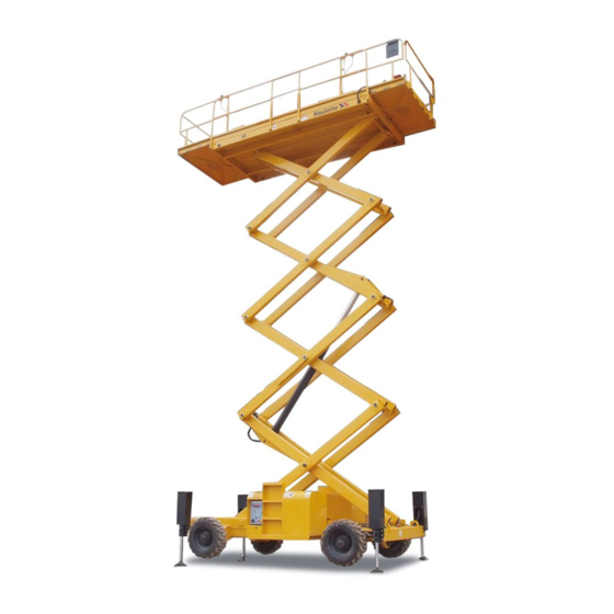
SCISSOR LIFT
H12 SD / SDX / SDE
H15 SD / SDX / SDE
H18 SDX
La Péronnière BP9 – 42152 L'HORME – France
( 04 77 29 24 24
7 04 77 31 28 11
E.Mail:
haulotte@haulotte.com
Web: http://www.haulotte.com
Table of
Contents
Previous
Page
Next
Page
1
2
3
4
5
Advertisement
Table of Contents
Troubleshooting
EMERGENCY PLATFORM LOWERING AND TROUBLESHOOTING
36
TROUBLESHOOTING
45
Need help?
Do you have a question about the H12 SD and is the answer not in the manual?
Ask a question
Questions and answers
Related Manuals for Haulotte H12 SD
Scissor Lifts Haulotte Compact 3368RT Operator's Manual
Engine-powered scissor lifts (120 pages)
Scissor Lifts Haulotte H12 SX Maintenance Book
(128 pages)
Scissor Lifts Haulotte H15 SD Operating And Maintenance Instructions Manual
(55 pages)
Scissor Lifts Haulotte H15 SDX Operating And Maintenance Instructions Manual
(55 pages)
Scissor Lifts Haulotte H18 SDX Operating And Maintenance Instructions Manual
(55 pages)
Scissor Lifts Haulotte Compact 8 Operator's Manual
Electric scissor lifts (140 pages)
Scissor Lifts Haulotte COMPACT 8 Operating And Maintenance Instructions Manual
Self-propelled scissor platform (80 pages)
Scissor Lifts Haulotte Compact 8 Operator's Manual
(124 pages)
This manual is also suitable for:
H12 sdx
H12 sde
H15 sd
H15 sdx
H15 sde
H18 sdx
Table of Contents
Save PDF
Print
Rename the bookmark
Delete bookmark?
Delete from my manuals?
Login
Sign In
OR
Sign in with Facebook
Sign in with Google
Upload manual
Upload from disk
Upload from URL


Need help?
Do you have a question about the H12 SD and is the answer not in the manual?
Questions and answers