Table of Contents
Advertisement
Quick Links
DFST-32-...-G2
Stopper cylinder
Instructions | Operating
8123248
2020-01
[8123250]
Translation of the original instructions
© 2020 all rights reserved to Festo SE & Co. KG
1
Applicable Documents
All available documents for the product è www.festo.com/sp.
2
Safety
2.1
Safety instructions
–
Take into consideration the ambient conditions at the location of use.
–
Only use the product in original status without unauthorised modifications.
–
Observe labelling on the product.
–
Store the product in a cool, dry, UV-protected and corrosion-protected envir-
onment. Ensure that storage times are kept to a minimum.
–
Prior to mounting, installation and maintenance work: Switch off compressed
air supply and secure it from being switched back on.
–
Observe tightening torques. Unless otherwise specified, the tolerance
is ± 20 %.
2.2
Intended Use
The stopper cylinder DFST is designed for use as a retractable fixed stop in order
to reach defined holding positions with transported material (e.g. on mounting or
sorting systems). The DFST sorts the stationary transported material in buffer
zones.
Fig. 1 Stopping transported material
2.3
Foreseeable misuse
With DFST-...-L: the toggle lever must not be overrun in the stop direction by the
transported material when the lever locking mechanism is active. Otherwise the
transported material will damage the locking mechanism.
2.4
Training of qualified personnel
Installation, commissioning, maintenance and disassembly should only be con-
ducted by qualified personnel.
The skilled personnel must be familiar with the installation of pneumatic control
systems.
3
Further information
–
Accessories è www.festo.com/catalogue.
–
Spare parts è www.festo.com/spareparts.
4
Service
Contact your regional Festo contact person if you have technical questions
è www.festo.com.
5
Product overview
5.1
Function
The stopper cylinder DFST is a double-acting cylinder. The piston rod is extended
with the toggle lever mechanism by pressurising the supply port 1 . The toggle
lever gently stops the incoming transported material with the integrated shock
absorber. The piston rod is retracted by pressurising the supply port 2 . The
stopper cylinder with spring return (not applicable for DFST-...-D/DL) can also be
set to single-acting. This is done by screwing a silencer into the supply port 1.
This makes sense if reduced extension velocities are sufficient.
Lever Locking Mechanism
With the stopper cylinder DFST-..-L with a factory-installed lever locking mechan-
ism, the toggle lever locks into its end position. When the stopper cylinder is
Festo SE & Co. KG
retracted, the toggle lever locking mechanism is automatically deactivated.
Ruiter Straße 82
5.2
73734 Esslingen
Germany
+49 711 347-0
www.festo.com
8123248
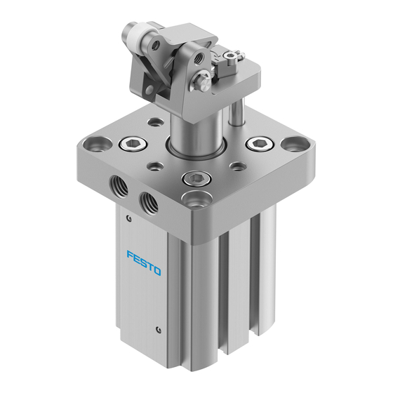
1 Supply port (extending, 2x)
2 Supply port (retracting, 2x)
3 Guide rod for protection against
rotation
4 Piston rod
5 Detent for knurled nut
6 Roller toggle lever
7 Stop roller
8 Thread for inductive proximity
sensor (2x)
Fig. 2 Product design
Structure
9 Lever locking mechanism (option-
al)
10 Knurled nut for setting the cush-
ioning
11 Stop for lever locking mechanism
12 Hole for mounting toggle lever
deactivation mechanism
13 Through-hole for mounting (4x)
14 Slot for proximity sensor (6x)
Advertisement
Table of Contents

Related Manuals for Festo DFST-32 G2 Series


Summary of Contents for Festo DFST-32 G2 Series
- Page 1 Instructions | Operating 8123248 2020-01 [8123250] 8123248 Translation of the original instructions © 2020 all rights reserved to Festo SE & Co. KG Applicable Documents All available documents for the product è www.festo.com/sp. Safety Safety instructions – Take into consideration the ambient conditions at the location of use.
- Page 2 Mounting Size Preparation X3 (minimum distance from the bottom of the pallet) [mm] 73.8 1) The dimensions refer to the position of the maximum energy absorption (knurled nut in the upper posi- tion). Tab. 1 Mounting Clearances Mounting Fig. 3 Maintain required distances •...
- Page 3 1. When used as a single-acting cylinder: screw a silencer into the supply port 1. Loosen the detent for the knurled nut 5. on the bottom (è www.festo.com/catalogue). 2. Turn knurled nut until the desired cushioning is reached. 2. Connect hoses to supply ports.
- Page 4 Technical Data Conveyor speed too Reduce velocity high Size Shock absorber faulty Replace shock absorber (è spare parts catalogue, www.festo.com) Constructive design Piston rod with toggle lever Piston rod in initial Tubing connection Check blanking plug Mode of operation –...
Need help?
Do you have a question about the DFST-32 G2 Series and is the answer not in the manual?
Questions and answers