Advertisement
Overview:
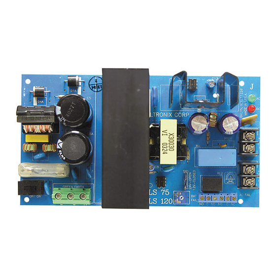
The OLS120 is a power limited supply/chargers that will convert a 115 VAC / 60Hz input, into a 12VDC or 24VDC
power limited output, with 4 amps of continuous supply current (see specifications).
Specifications:
• Switch selectable 12VDC or 24VDC power limited output.
• Input 115VAC / 60Hz, .95 amp.
• Maximum charge current .5 amp.
• 4 amps continuous supply current at 12VDC and 24VDC.
• Filtered and electronically regulated outputs.
• Built-in charger for sealed lead acid or gel type batteries.
• Automatic switch over to stand-by battery when AC fails
(zero voltage drop).
• AC input and DC output LED indicators.
• AC fail supervision (form "C" contacts).
• Low battery supervision (form "C" contacts).
• Short circuit and thermal overload protection.
• Includes battery leads.
Specified at 25˚ C ambient.
Power Supply Voltage Output Specifications:
Output VDC
12VDC
24VDC
Installation Instructions:
The OLS120 should be installed in accordance with The National Electrical Code
and all applicable Local Regulations.
1. Mount the OLS120 in desired location.
2. Set the OLS120 to desired DC output voltage via SW1 (see power supply voltage output selection chart).
3. Connect AC power to terminals marked [L & N], connect ground to terminal marked [G].
Use 18 AWG or larger for all power connections (Battery, DC output).
Use 22 AWG to 18 AWG for power limited circuits (AC Fail/Low Battery reporting).
Keep power limited wiring separate from non-power limited wiring
(115VAC / 60Hz Input, Battery Wires). Minimum .25" spacing must be provided.
4. Connect devices to be powered to terminals marked [+ DC -- ].
Note: It is good operating practice to measure and verify output voltage before
connecting devices to ensure proper operation of equipment.
5. When the use of stand-by batteries are desired, they must be lead acid or gel type.
Connect battery to terminals marked [- BAT +] (battery leads included).
Use two (2) 12VDC batteries connected in series for 24VDC operation.
Note: When batteries are not used a loss of AC will result in the loss of output voltage.
6. Connect appropriate signaling notification devices to AC Fail & Low battery supervisory
relay outputs marked [N.C., C, N.O.].
IIOLS120 - Rev. 101899
OLS120
Supervised Power Supply/Charger
Switch Position
SW 1 - Closed
SW1 - Open
Max. Load DC
4 amps
4 amps
Advertisement
Table of Contents

Related Manuals for Altronix OLS120


Summary of Contents for Altronix OLS120
- Page 1 OLS120 Supervised Power Supply/Charger Overview: The OLS120 is a power limited supply/chargers that will convert a 115 VAC / 60Hz input, into a 12VDC or 24VDC power limited output, with 4 amps of continuous supply current (see specifications). Specifications: • Switch selectable 12VDC or 24VDC power limited output.
- Page 2 OLS 120 FAIL C NC NO C Altronix is not responsible for any typographical errors. Product specifications are subject to change without notice. MEMBER Altronix Corp. 140 58th Street, Brooklyn, New York 11220 USA, 718-567-8181, fax: 718-567-9056 website: www.altronix.com, e-mail: info@altronix.com, Made in U.S.A.
Need help?
Do you have a question about the OLS120 and is the answer not in the manual?
Questions and answers