
Related Manuals for H3C SR8800 Series


Summary of Contents for H3C SR8800 Series
- Page 1 H3C SR8800 10G Routers Installation Guide New H3C Technologies Co., Ltd. http://www.h3c.com.hk Document version: T2-080412-20170331-C-3.14...
- Page 2 Copyright © 2007-2017, New H3C Technologies Co., Ltd. and its licensors All rights reserved No part of this manual may be reproduced or transmitted in any form or by any means without prior written consent of New H3C Technologies Co., Ltd.
-
Page 3: Command Conventions
Preface The H3C SR8800 10G Routers Installation Guide includes seven chapters, which describe the components, installation, debugging, and hardware maintenance of the H3C SR8800 10G Routers. This preface includes: Audience. • • Conventions. Obtaining documentation. • Technical support • •... -
Page 4: Gui Conventions
GUI conventions Convention Description Window names, button names, field names, and menu items are in Boldface. For Boldface example, the New User window opens; click OK. > Multi-level menus are separated by angle brackets. For example, File > Create > Folder. Symbols Convention Description... -
Page 5: Obtaining Documentation
It is normal that the port numbers, sample output, screenshots, and other information in the examples differ from what you have on your device. Obtaining documentation To access the most up-to-date H3C product documentation, go to the H3C website at http://www.h3c.com.hk. To obtain information about installation, configuration, and maintenance, click http://www.h3c.com.hk/Technical_Documents... - Page 6 Contents Product overview ·························································································································································· 1 Chassis views ···································································································································································· 1 SR8802 chassis views ············································································································································· 2 SR8805 chassis views ············································································································································· 4 SR8808 chassis views ············································································································································· 6 SR8812 chassis views ············································································································································· 8 Power supply system ························································································································································· 9 ...
- Page 7 Installation procedure ··········································································································································· 37 Installing a subcard ························································································································································ 37 Installation preparation ········································································································································· 38 Installation procedure ··········································································································································· 38 Connecting power cords ··············································································································································· 39 Prerequisites ··························································································································································· 39 Connecting an AC power cord ··························································································································· 39 Connecting a DC power cord ······························································································································ 42 ...
- Page 8 Cleaning the air filter of a power module ··················································································································· 72 Replacing a card ···························································································································································· 72 Preparing for the replacement ····························································································································· 73 Replacement procedure ········································································································································ 73 Replacing a subcard ······················································································································································ 74 Replacement procedure ········································································································································ 74 Replacing a fan tray ······················································································································································...
- Page 9 Affixing a label to a signal cable ······················································································································ 110 Affixing a label to a power cord ······················································································································· 111 Affixing a generic label ······································································································································ 112 Affixing a label to a device ································································································································ 113 Guidelines ····································································································································································· 113 Examples ·······································································································································································...
-
Page 10: Product Overview
Product overview The H3C SR8800 routers include the models in Table Table 1 SR8800 router chassis Chassis Power input Card slot orientation MPU slots LPU slots SR8802 AC/DC Horizontal SR8805 AC/DC Horizontal SR8808 AC/DC Vertical SR8812 AC/DC Horizontal NOTE: A main processing unit (MPU) is the supervisor engine of a router, and a line processing unit (LPU) •... - Page 11 SR8802 chassis views Figure 1 SR8802 front view (1) ESD-preventive wrist strap port (2) MPU slots (slots 0 and 1) (3) LPU slots (slots 2 and 3) (4) Power module slots NOTE: • Slot 0 is for an MPU, while Slot 1 can be used for an MPU or LPU. You can install one or two power modules, but intermixing of AC and DC power modules is not allowed.
- Page 12 Figure 2 SR8802 rear view (1) Rear cover handle (2) Grounding screw (3) Fan tray...
- Page 13 SR8805 chassis views Figure 3 SR8805 front view (1) ESD-preventive wrist strap port (2) MPU slots (slots 0 and 1) (3) LPU slots (slots 2 to 6) (4) Power module slots (5) PoE power entry module (reserved, currently not available) NOTE: You can install one or two power modules, but intermixing of AC and DC power modules is not allowed.
- Page 14 Figure 4 SR8805 rear view (1) Rear cover handle (2) Grounding screw (3) Fan tray...
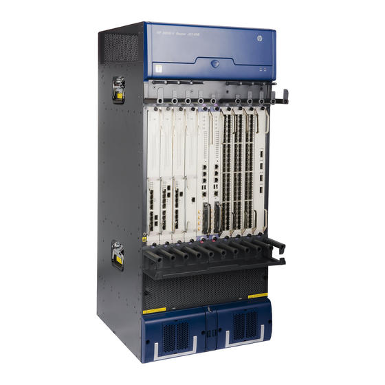
- Page 15 SR8808 chassis views Figure 5 SR8808 front view (1) Fan tray (2) MPU slots (slots 4 and 5) (3) LPU slots (slots 0 to 3, 6 to 9) (4) Cable management bracket (5) Power module slots (6) PoE power entry module (reserved, currently not available) (7) ESD-preventive wrist strap port NOTE: You can install one or two power modules, but intermixing of AC and DC power modules is not allowed.
- Page 16 Figure 6 SR8808 rear view (1) Air filter (2) Grounding screw (3) Rear cover handles...
- Page 17 SR8812 chassis views Figure 7 SR8812 front view (1) ESD-preventive strap port (2) LPU slots (slots 0 to 5, 8 to 13) (3) MPU slots (slots 6 and 7) (4) Power module slots (5) PoE power entry module (reserved, currently not available) NOTE: You can install one or two power modules, but intermixing of AC and DC power modules is not allowed.
-
Page 18: Power Supply System
(3) Fan tray Power supply system The SR8800 routers support both AC and DC power modules, but the power modules installed on an SR8800 router must be the same model. H3C recommends that you install two power modules for redundancy. Table 2 lists the power modules available for the SR8800 routers. -
Page 19: Ac Power Modules
NOTE: Use the NEPS2000-D for the SR8808 and SR8812 routers only when the number of cards is small. AC power modules Table 3 AC power module specifications Item NEPS800-A NEPS1800-A Rated input 100 VAC to 240 VAC @ 50 Hz or 60 Hz 100 VAC to 240 VAC @ 50 Hz or 60 Hz voltage range Max input... -
Page 20: Dc Power Modules
Figure 10 NEPS3500-A power frame (1) Power input LED (2) Power output LED (3) Power fault LED (4) Power modules You can install one or two NEPS1800-A AC power modules into the NEPS3500-A power frame. If two NEPS1800-A power modules are installed, the maximum output power is 3500 W. Table 4 AC power module LED description Color Status... - Page 21 Item NEPS1300-D NEPS2000-D NEPS3500-D 3500 W Max output power 1300 W 2000 W (3200 W @ –40 VDC) Figure 11 NEPS1300-D (1) Power input LED (2) Power output LED (3) Power fault LED Figure 12 NEPS2000-D DC power module (1) Power input LED (2) Power output LED (3) Power fault LED...
-
Page 22: Cooling System
Figure 13 NEPS3500-D DC power module (1) Power input LED (2) Power output LED (3) Power fault LED Table 6 DC power module LED description Color Status Description Steady on Power is being correctly input. IN (input) Green The power module is absent or has input voltage error. Steady on The power module is correctly outputting power. - Page 23 Figure 14 Fan trays (1) RUN LEDs (2) ALM LEDs Table 7 Description of fan LEDs Color Status Description The fan tray has failed. Green Steady on The fan tray is operating correctly. The fan tray is in a normal state. Steady on The fan tray is faulty.
- Page 24 Airflow design for the SR8802 and SR8805 and SR8812 The chassis and power modules of the SR8802, SR8805, and SR8812 routers use separate air aisles. The airflow for the power module section at the bottom is from front to rear, and the airflow for the chassis is from left to right, as shown in Figure Figure 15 SR8805 airflow...
- Page 25 Figure 16 SR8808 airflow (1) Chassis air intake (2) Chassis air outlet (3) Power module air intake (4) Power module air outlet If you have installed a rear air deflector for the SR8808 router, the fan tray cannot pull ambient air in from the rear but can still blow hot air out of the rear.
-
Page 26: Preparing For Installation
Preparing for installation Safety recommendations To avoid any equipment damage or bodily injury caused by improper use, read the following safety recommendations before installation. Note that the recommendations do not cover every possible hazardous condition. General safety recommendations • Take adequate safety measures to avoid injury and router damage. For example, wear an ESD wrist strap. -
Page 27: Router Moving
Make sure the ESD wrist strap is correctly grounded. Figure 17 Attaching an ESD wrist strap Router moving When you move an H3C SR8800 router, follow these guidelines: Remove all the external cables (including the power cables) before moving the chassis. •... -
Page 28: Examining The Installation Site
Examining the installation site The H3C SR8800 routers can only be used indoors. To make sure the router operates correctly and to prolong its service lifetime, the installation site must meet the requirements in this section. Weight support Evaluate the floor loading as compared to the actual weight of the router and its accessories (such as rack, chassis, cards, and power supply units), and make sure the floor can support the weight of the rack and the router chassis. -
Page 29: Emi Requirements
Cleanness Dust buildup on the chassis might result in electrostatic adsorption, which causes poor contact of metal components and contact points, especially when indoor relative humidity is low. In the worst case, electrostatic adsorption can cause communication failure. Table 10 Dust concentration limit in the equipment room Substance Concentration limit (particles/cu m) Dust particles... -
Page 30: Power Supply
Power supply Perform the following steps to meet the power supply requirements of the SR8800 routers: Calculate the system power consumption. Select power modules according to the system power consumption and power supply mode. To ensure normal operation of the router, make sure the maximum output power of the power modules is greater than the system power consumption of the router (reserve certain power for redundancy). - Page 31 Figure 18 Rack width Make sure the available space between the front rack post and the outer edge of the front rack door • is greater than 125 mm (4.92 in) and the depth of the rack (distance between the front and back doors) is greater than 800 mm (31.50 in).
-
Page 32: Installation Tools
The slide rails (or rack shelves) can support the weight of the router chassis and its accessories. • • The rack can be correctly grounded. The rack has good ventilation system, and the porosity of the front and back doors is greater than •... - Page 33 The rack accessories and installation tools are not included in this section. The accessories and installation tools might vary depending on the rack model. For more information, see the installation guide of the corresponding rack.
-
Page 34: Inspecting The Router
Using the packing list supplied with your router, inspect the router to be sure that you have all the items listed in the packing list, and verify that the router was not damaged during shipment. If anything is damaged or missing, contact the H3C customer representative immediately. Installing the router in a rack IMPORTANT: An SR8800 router can be installed only in a 4-post 19-inch standard rack. -
Page 35: Installation Preparation
Slide rails or rack shelves are not provided with the router. Prepare them yourself, or order them from H3C. The appearance and installation methods of slide rails depend on the slide rail types. The following uses a 19-inch rack as an example to describe the installation procedures. - Page 36 Figure 21 Installing the slide rails (1) Middle of the narrower metal area between holes (2) 1 RU To ensure stability of the rack, install the slide rails to the lowest possible position when installing a single router on the rack. To install multiple routers on the rack, mount the heaviest router at the bottom of the rack.
-
Page 37: Installing The Cable Management Brackets
Figure 22 Installing the cage nuts NOTE: When preparing for installation, make sure the total height of the routers to be installed is no higher than the height of the rack, and reserve enough clearance for cable routing. Installing the cable management brackets Installing the cable management brackets on the SR8808 The SR8808 has two cable management brackets. - Page 38 Figure 23 Installing cable management brackets on an SR8808 Installing the cable management brackets on the SR8802/SR8805/SR8812 For the SR8802/SR8805/SR8812, install the cable management brackets to the mounting brackets (cable management brackets and mounting brackets are required at both sides of the chassis). Figure 24 shows how to install a right cable management bracket.
-
Page 39: Installing The Mounting Brackets
Figure 24 Installing the cable management bracket for the SR8802/SR8805/SR8812 Installing the mounting brackets Before installing the router to the rack, install the mounting brackets to the chassis. Figure 25 shows how to install the mounting brackets to an SR8805 router. Figure 25 Installing the mounting brackets... -
Page 40: Installing An Impedance Carrier (Optional)
Installing an impedance carrier (optional) An impedance carrier is shipped with the SR8808. You can install the impedance carrier at the rear of the chassis (where an air filter is located) to block the airflow from entering the rear of the chassis. Install an impedance carrier where routers adopt front to rear airflow. -
Page 41: Verifying The Installation
Mount the router on the rack shelf or slide rails in cooperation with several people. Slide the router into the rack until the mounting brackets on the router touch the front rack posts. Secure the mounting brackets to the rack posts with mounting screws. See Figure Figure 27 Installing the router in a standard 19-inch rack If the screw holes on the mounting brackets cannot align with the cage nuts on the rack, check that the... -
Page 42: Installing The Power System
Installing the power system The SR8800 routers support both AC and DC power supply modes, but the power modules installed on an SR8800 router must be the same model. H3C recommends that you install two power modules for redundancy. -
Page 43: Installing A Dc Power Module
Installation preparation Put on an ESD wrist strap and make sure it is correctly grounded. Remove the blank panel (if any) from the slot to be used. To ensure good ventilation, install blank panels in unused slots. CAUTION: Hold a power module by the bottom when moving it. Never attempt to lift a power module with its •... -
Page 44: Installing An Ac Power Module
Installing an AC power module Installing NEPS800-A and NEPS2000-A AC power modules The NEPS800-A and NEPS2000-A power modules are installed in the same way. The following takes an NEPS2000-A for example. To install an NEPS2000-A AC power module: Remove the air filter frame of the power module, and gently pull the AC power module handle out. Holding the handle of the power module with one hand and supporting the bottom of the power module with the other hand, insert the power module slowly along the guide rails to fully seat it in the backplane. -
Page 45: Installing A Card
For a router that requires power module redundancy, install the same number of power modules in the two power frames. Installing an NEPS1800-A AC power module Pull the handle of the NEPS1800-A AC power module downward to the unlock position. Gently push the power module into the AC power frame (NEPS3500-A) to fully seat the power module in the power frame backplane. -
Page 46: Installation Procedure
Installation procedure Remove the protection cover before installing a card: Put on an ESD wrist strap and then loosen the captive screws that fix the card to the protection cover with a Philips screwdriver. Pull the card out of the protection cover gently, as shown in Figure Keep the protection cover for future use. - Page 47 Installation preparation Put on an ESD wrist strap and make sure it is correctly grounded. Remove the blank panel (if any) from the slot to be used on the SPE base card. To ensure good ventilation, install blank panels in unused slots. Unpack the subcard.
-
Page 48: Connecting An Ac Power Cord
Figure 35 Installing a subcard Connecting power cords Prerequisites Check the following items before connecting power cords: For lightning protection, the AC power should be led through an external lightning device into the • SR8800 router. For more information, see "Appendix C Lightning protection."... - Page 49 The NEPS800-A and NEPS2000-A AC power cords are connected in the same way. The following takes an NEPS2000-A for example. To connect an AC power cord Install a bail latch to the left of the front panel of the power module, and pull it to the right. Plug the AC power cord into the AC power receptacle on the power module.
- Page 50 Figure 37 Bail latch and AC power cord Attach the bail latch to the plug of the AC power cord. Figure 38 Attaching the bail latch to the plug of the AC power cord Connect the plug of the AC power cord to the power receptacle of the power module, as shown in callout 1 on Figure 39.
-
Page 51: Connecting A Dc Power Cord
Figure 40 Connecting the power cord to the 16A AC power socket Socket Connecting a DC power cord The DC power cords of the NEPS1300-D, NEPS2000-D, and NEPS3500-D are connected in a similar way. The NEPS2000-D is used in this example. WARNING! A DC power cord is fixed by screws and the wiring terminals of a DC power module. - Page 52 Figure 41 Connecting a DC power cord Verifying the installation WARNING! Make sure you have turned off the power before checking the installation to avoid bodily injury and router damage. After the installation is completed, verify the installation against the following list. Ensure that all check results are positive.
-
Page 53: Connecting The Router To The Network
Connecting the router to the network Logging in to the router Logging in through the console port is the most common way to log in to a router. It is also the prerequisite to configuring other login methods. Connecting the console cable Introduction A console cable is an 8-core shielded cable, with a crimped RJ-45 connector at one end for connecting to the console port of the router, and a DB-9 female connector at the other end for connecting to the serial... -
Page 54: Setting Up A Configuration Environment
Figure 43 Connecting the router and the PC through the console port Before logging in to the router through the console port, use a console cable to connect the serial port of your PC (or terminal) to the console port of your router. When you remove the console cable, first unplug the RJ-45 end, and then the DB-9 end. - Page 55 Figure 45 Setting the serial port used by the HyperTerminal connection Set Bits per second to 9600, Data bits to 8, Parity to None, Stop bits to 1, and Flow control to None, and click OK. Figure 46 Setting the serial port parameters Select File >...
- Page 56 Figure 47 HyperTerminal window On the Settings tab, set the emulation to VT100 and click OK. H3C recommends that you select the Windows keys option. Figure 48 Setting the terminal emulation in Test Properties dialog box...
-
Page 57: Powering On The Router
System is starting... Booting Normal Extend BootWare The Extend BootWare is self-decompressing......Done! **************************************************************************** H3C SR8800 BootWare, Version 1.10 **************************************************************************** ---- More ---- The router initiates the power-on self-test (POST) and the results are displayed at the console terminal. Board self testing...... -
Page 58: Verification After Power-On
Press ENTER to get started. Press Enter to begin configuring the router at the prompt: <H3C> The SR8800 router provides a CLI. For more information about the CLI, see H3C SR8800 Router Series Fundamentals Configuration Guide. NOTE: The output depends on your router model. - Page 59 Connecting the router to the network Connecting the router to the network through an AUX cable You need an AUX cable when configuring a router with the remote modem dial-up approach. An AUX cable is an 8-core shielded cable. At one end of the cable is an RJ-45 connector and at the other end is a DB-9 (male) connector.
-
Page 60: Installing A Transceiver Module
Precautions Follow these precautionary steps: • When selecting a fiber network facility, make sure the type of the connector and the fiber matches the adopted fiber port. Before connecting a fiber, make sure the optical power at the receiving end does not exceed the •... -
Page 61: Connection Procedure
Figure 50 Installing an SFP module IMPORTANT: • Do not remove the dust plug of the SFP module port before installing an optical fiber. For an SFP module installed with an optical fiber, remove the fiber before you install the SFP module into •... -
Page 62: Cable Routing Recommendations
The router is installed. The installation involves the following materials: M5×10 self-tapping screws (two screws for one FMT) Installation procedure To install the fiber management tray: Align the FMT and the installation holes on the column of the rack. Use a Phillips screwdriver to fix each FMT with two M5×10 self-tapping screws. Figure 52 Installing FMTs Cable routing recommendations Interface cables and power cords should be separately routed. -
Page 63: Hardware Management
<Sysname> display device manuinfo slot 3 Slot 3: DEVICE_NAME : SPC-1010-II DEVICE_SERIAL_NUMBER : 210231A0E50103000002 MAC_ADDRESS : 000f-e200-5600 MANUFACTURING_DATE : 2011-02-28 VENDOR_NAME : H3C Slot 3 Subslot 1: DEVICE_NAME : PIC-TCP8L DEVICE_SERIAL_NUMBER : 210231A85JH105000015 MAC_ADDRESS : NONE MANUFACTURING_DATE : 2010-05-24 VENDOR_NAME... -
Page 64: Rebooting Your Router
Sub1 PIC-TCP8L Normal NONE Absent NONE NONE Absent NONE NONE Absent NONE Table 18 Command output Field Description Slot No. Slot number of a card. Hardware type of a card: • Specific card model—Type of a card (such as SPE- 1 010-II), which is the same as the mark on the card. - Page 65 For data security, if you reboot the router while the router is performing file operations, the router does not reboot. The precision of the rebooting timer is 1 minute. One minute before the rebooting time, the router prompts "REBOOT IN ONE MINUTE" and reboots in one minute. To reboot a router: Task Command...
-
Page 66: Configuring Temperature Alarm Thresholds For A Card
Configuring temperature alarm thresholds for a card Configuring temperature alarm thresholds for a card Use the following command to set temperature alarm thresholds for a card. When the temperature of a card exceeds a threshold, the router generates alarm signals. To configure temperature alarm thresholds for a card: Step Command... -
Page 67: Configuring In-Service Hardware Failure Diagnosis
Configuring in-service hardware failure diagnosis A hardware failure might cause traffic forwarding failures and service interruption. To improve the automatic failure detection and handling capabilities of the router, you can configure in-service hardware failure diagnosis. The in-service hardware failure diagnosis includes the detection for chips, cards, and the forwarding service, and automatic fix actions taken for the detected failures. -
Page 68: Verifying And Diagnosing Transceiver Modules
Table 21 Command output Field Description Alarm severity. Level In the descending order, the alarm severity levels include ERROR, WARNING, NOTICE, and INFO. Info Detailed alarm information. Slot n board state is faulty. Card n is faulty. The reason might be the card is booting or the card fails. Verifying and diagnosing transceiver modules Introduction to transceiver modules There are two types of commonly used transceiver modules, as shown in... - Page 69 Connector Type : LC Wavelength(nm) : 850 Transfer Distance(m) : 550(50um),270(62.5um) Digital Diagnostic Monitoring : YES Vendor Name : H3C Ordering Name : SFP-GE-SX-MM850 Table 23 Command output Field Description Type of the connectors of the transceiver module: • Optical connectors, including SC (SC connector, developed by NTT) and LC Connector Type (LC connector, 1.25 mm/RJ-45 optical connector developed by Lucent).
-
Page 70: Diagnosing Transceiver Modules
Field Description Manufacturing Date Manufacturing date of the transceiver module. Vendor Name Name of vendor who customizes the transceiver module. Diagnosing transceiver modules The device provides the alarm function and digital diagnosis function for transceiver modules. When a transceiver module fails or inappropriately work, you can check for alarms present on the transceiver module to identify the fault source or examine the key parameters monitored by the digital diagnosis function, including the temperature, voltage, laser bias current, TX power, and RX power. - Page 71 Field Remarks Transceiver info checksum error Transceiver information checksum error Transceiver type and port configuration mismatch Transceiver type does not match port configuration. Transceiver type not supported by port hardware Transceiver type is not supported on the port. RX loss of signal RX signal is lost.
- Page 72 Table 26 Command output Field Description Fault detection information of the transceiver module plugged in the transceiver diagnostic information interface. Current diagnostic parameters Current fault detection parameters. Temp.(°C) Digital diagnosis parameter-temperature, in °C, with the precision to 1°C. Voltage(V) Fault detection parameter-voltage, in V, with the precision to 0.01 V. Fault detection parameter-bias current, in mA, with the precision to 0.01 Bias(mA) Fault detection parameter-RX power, in dBM, with the precision to 0.01...
-
Page 73: Troubleshooting
Troubleshooting This chapter describes how to troubleshoot the SR8800 router installation failures. The power supply system, fans, and cards of an SR8800 router have multiple LEDs, through which you can locate the failures. Configuration terminal problems If the configuration environment setup is correct, the configuration terminal displays boot information when the router is powered on. -
Page 74: Power Supply System Failure
Power supply system failure Table 27 AC power module LED description Color Status Description Steady on Power is being correctly input. Input Green The power module is absent or has input voltage error. Steady on The power module is correctly outputting power. Output Green The power module has output voltage error or is absent. -
Page 75: Fan Failure
Fan failure Table 29 Fan LED description Color Status Description The fan tray has failed. Green Steady on The fan tray is operating correctly. The fan tray is in a normal state. Steady on The fan tray is faulty. When the RUN LED is off or the ALM LED is on, the fan fails. To troubleshoot the fan: If both LEDs are off, verify that the power module is operating correctly. -
Page 76: Lpu Failure
The appearance of the SR8800 MPUs varies by model. Figure 53 takes SR02SRP1F3 as an example. When the MPU operates correctly, the RUN LED (callout 6 in Figure 53) flashes, and the ALM LED (callout 7 in Figure 53) is off. When the RUN LED is off, the MPU fails. To troubleshoot the MPU: Verify that the power module is operating correctly. -
Page 77: Technical Support
• Brief problem description • Brief explanation of the troubleshooting measures that have been taken • You can contact the customer service through the customer service hotline, the H3C website, or email. Customer service hotline: 400-810-0504 Website: http://www.h3c.com E-mail: service@h3c.com... -
Page 78: Replacement Procedures
Replacement procedures This chapter describes how to replace modules for the SR8800 router, and includes these sections: H3C recommends that you place a removed module in an antistatic bag or its original shipping materials. Replacing a power supply system Power modules for the SR8800 routers are hot swappable. - Page 79 Figure 54 Replacing a DC power module (A) DC power module to be removed (B) DC power module to be installed Replacing an AC power module Replacing an NEPS800-A or NEPS2000-A AC power module The procedures for replacing an NEPS800-A or NEPS2000-A AC power module are the same as replacing a DC power module.
- Page 80 Supporting the bottom of the power frame with one hand and holding the power frame handle with the other hand, gently pull the AC power frame out along the guide rails. Slowly push the new power frame into the slot along the guide rails to fully seat it in the backplane. Use a Phillips screwdriver to fasten the captive screws on both sides of the power frame.
-
Page 81: Replacing A Card
Cleaning the air filter of a power module To guarantee well ventilation of a power module, H3C recommends that you clear the air filter of the power module monthly. The NEPS1800-A power module does not have an air filter. To clean the air filter of a power module: Using your thumb and index finger to hold the upper and lower edges of the air filter frame, gently remove the air filter frame. -
Page 82: Replacement Procedure
Preparing for the replacement Put on an ESD wrist strap, and make sure the wrist strap makes good skin contact and is well grounded. Remove the blank panel (if any) from the slot to be used and keep the removed blank panel for future use. -
Page 83: Replacing A Subcard
Figure 59 Replacing a card Replacing a subcard This section describes how to replace an MIC subcard on an MPE base card, an PIC subcard on a SPE base card. MIC subcards are hot-swappable; PIC subcards are not hot-swappable. Replacement procedure Put on an ESD wrist strap and loosen the captive screws on the subcard to be replaced. -
Page 84: Replacing A Fan Tray
Figure 60 Replacing a subcard (A) Subcard to be removed (B) Subcard to be installed Replacing a fan tray CAUTION: To avoid injury, do not touch any wires, terminals, and parts with a high-voltage hazard sign. • • To replace a fan tray with the router running, pull out the fan tray after it stops rotating. Keep your hands away from the spinning fan blades when removing the fan tray. - Page 85 Put on an ESD wrist strap and loosen the captive screws on the fan tray. Holding the fan tray handle with one hand and supporting the fan tray bottom with the other hand, pull out the fan tray along the guide rails. Put the removed fan tray on an antistatic mat or into its original shipping materials.
-
Page 86: Replacing A Chassis Air Filter
Figure 62 Replacing a fan tray for an SR8808 (A) Fan tray to be removed (B) Fan tray to be installed Replacing a chassis air filter Clean air filters every three months to guarantee adequate ventilation and avoid over-temperature. No chassis air filter is shipped with the router by default. -
Page 87: Replacing A Cf Card
Replacing the air filter for an SR8802/SR8805/SR8812 Loosen the captive screws on the air filter, as shown in callout 1 on Figure Seizing the captive screws on the air filter, slowly pull the air filter out of the chassis, as shown in callout 2 on Figure Install the cleaned air filter to the router. - Page 88 CF card again. For more information about the umount and mount commands, see H3C SR8800 Router Series Fundamentals Command Reference. Use a Phillips screwdriver to loosen the screw at the right side of the CF card cover, and pull the CF card cover outward.
-
Page 89: Replacing A Transceiver Module
Figure 66 Replacing a CF card Replacing a transceiver module The replacement procedures of XFP and SFP transceiver modules are similar. This section takes an SFP transceiver module as an example. CAUTION: When installing or removing an SFP transceiver module, do not touch the golden finger of the SFP transceiver module. - Page 90 Figure 67 Removing an SFP transceiver module Figure 68 Installing an SFP transceiver module NOTE: Remove the fibers, if any, from the SFP transceiver module before installing it.
-
Page 91: Environment Requirements
Appendix A Technical specifications Environment requirements Temperature Range • Long term: 0°C to 45°C (32°F to 1 13°F) • Operating temperature Short term: –10°C to +55°C (14°F to 131°F) (up to 96 hours of continuous operation within less than 15 days in one year) Operating humidity (noncondensing) 5% to 95% Storage temperature... -
Page 92: Card Specifications
Card specifications All cards are hot-swappable, except for the PIC subcards. Table 30 Card specifications Power Card model Net weight Dimensions (H × W × D) consumption SR02SRP1M3 70 W to 90 W 3.85 kg (8.49 lb) 40 × 400 × 380 mm (1.57 × 15.75 × 14.96 in) SR02SRP1E3 70 W to 90 W 3.65 kg (8.05 lb) - Page 93 Power Card model Net weight Dimensions (H × W × D) consumption 16.32 W to 23.5 PIC-GT20R 0.65 kg (1.43 lb) 37 × 165 × 142 mm (1.46 × 6.50 × 5.59 in) 12.47 W to 23.7 PIC-XP1L 0.45 kg (0.99 lb) 18 ×...
- Page 94 Power Card model Net weight Dimensions (H × W × D) consumption IM-NAM-II 94 W to 107 W 3.40 kg (7.50 lb) 40 × 400 × 380 mm (1.57 × 15.75 × 14.96 in) IM-FW-II 84.88 W to 120 W 3.52 kg (7.76 lb) 40 ×...
- Page 95 SR02SRP1 SR02SRP SR02SRP SR02SRP SR02SRP2 SR02SRP1 SR02SRP Item • 1 console port • 1 AUX port • • 1 network 1 console port • 1 console port management port • 1 AUX port • 1 AUX port • 1 RS-232/485 port •...
- Page 96 Available transceiver modules Model Description and cables • Ethernet XFP fiber module 4-port 10GBASE-R/W optical Ethernet interface SPC-XP4LA • Ethernet and POS XFP fiber card (XFP, LC) module 48-port 10/100/1000BASE-T electrical SPC-GT48LA RJ-45 cable Ethernet interface card (RJ-45) • FE SFP fiber module •...
-
Page 97: Subcard Specifications
Table 31 MPE base card specifications Model Number of slots Description MPE-1004 Multi-service base card NOTE: On the MPE-1004, slot 3 does not support the MIC-GP8L, and slot 4 does not support the MIC-GP8L or the MIC-ET16L. Subcard specifications No subcards are directly installed in the router. The PIC subcard is installed in the SPE base card. - Page 98 Available transceiver modules Model Description and cables • 2.5G SFP fiber module 2-port OC-48c/STM-16c POS optical interface • GE SFP fiber module PIC-PS2G4L (SFP, LC) + 4-port 1000BASE-X optical interface • GE CWDM SFP fiber module card (SFP, LC) • GE SFP copper module •...
- Page 99 Available transceiver modules Model Description and cables • FE SFP fiber module 1-port OC-12/STM-4 channelized to • 622M SFP fiber module OC-12c/STM-4c or E3/T3 CPOS optical interface • GE SFP fiber module PIC-CHS1G4L (SFP, LC) + 4-port 1000BASE-X optical interface •...
-
Page 100: Oaa Module Specifications
Available transceiver modules Model Description and cables 4-port OC-3c/STM-1c POS/ATM or 1-port • 155M SFP fiber module MIC-SP4L OC-12c/STM-4c POS/ATM optical interface card • 622M SFP fiber module (SFP, LC) NOTE: When the MIC-SP4L operates as a 1-port OC-12c/STM-4c POS/ATM optical interface card, only port 1 is available. - Page 101 You can order transceiver modules supported by the LPU interfaces. For the supported transceiver modules, see "Card specifications." For more information about transceiver modules, see H3C Transceiver Modules User Guide. SFP modules Before you purchase an SFP module, make sure you have read the following guidelines and restrictions: The SFP-GE/FE-LX10-SM1310 is installed in a 1000-Mbps fiber port, and it provides the port speed •...
- Page 102 Type Available models • SFP-GE-LH70-SM1470-CW • SFP-GE-LH70-SM1490-CW • SFP-GE-LH70-SM1510-CW • SFP-GE-LH70-SM1530-CW GE CWDM SFP fiber module • SFP-GE-LH70-SM1550-CW • SFP-GE-LH70-SM1570-CW • SFP-GE-LH70-SM1590-CW • SFP-GE-LH70-SM1610-CW • SFP-GE-T GE SFP copper module • SFP-GE-T-D • SFP-2.5G-LX-SM1310 • SFP-2.5G-LH15-SM1310 2.5G SFP fiber module •...
-
Page 103: Fan Tray Specifications
Choose power modules based on your actual needs. Make sure the maximum output power of the • power modules exceeds the system power consumption. (H3C recommends reserving a certain power de-rating value.) For the maximum output power of a single power module, see Table H3C recommends you to configure N+1 or N+M power module redundancy. - Page 104 An NEPS3500-A AC power frame can function properly only after you install one or two • NEPS1800-A AC power modules to it. Table 38 Electrical parameters of power system Rated input Max input Max input Model Description Max output power voltage range voltage range current...
- Page 105 Countries or regions Countries or where the type of Other countries or Connector power cords conforms regions seldom Code (Length) regions using this type of type to local safety using this type of power cords regulations and can be power cords used legally Mexico, Argentina, 0404A063 (3...
- Page 106 Countries or regions Countries or where the type of Other countries or Connector power cords conforms regions seldom Code (Length) regions using this type of type to local safety using this type of power cords regulations and can be power cords used legally 0404A060 (3 Malaysia, Singapore,...
- Page 107 Countries or regions Countries or where the type of Other countries or Connector Code power cords conforms regions seldom regions using this type type (Length) to local safety using this type of of power cords regulations and can be power cords used legally 0404A0C2 Mainland China...
-
Page 108: Power Module Leds
Appendix B LEDs Power module LEDs Table 40 AC power module LED description Status Description Steady on Power is being correctly input. Input The power module is absent or has input voltage error. Steady on The power module is correctly outputting power. Output The power module has output voltage error or is absent. -
Page 109: Cf Card Status Led
MPU LEDs An SR8800 MPU has the following LEDs (from left to right): • CF card status LED Network management port LEDs • LPU status LEDs • MPU status LEDs • Figure 69 MPU LEDs (2) Network management port LED (3) Network management port LED (1) CF card status LED (CFS) (ACT) - Page 110 Network management port LEDs Table 44 Network management port LED description Status Description No link is present. LINK Steady on A link is present. No data is being transmitted or received. Flashing Data is being transmitted and/or received. LPU status LEDs Table 45 LPU status LED description Status Description...
-
Page 111: Spc Card Leds
Table 47 shows the LED description of an SR02SRP1F3/SR02SRP2F3 MPU. Table 47 MPU status LED description Status Description The switching fabric module is in the operating state, or is Steady on starting up. SFS (green) The switching fabric module is in the standby state. Steady on The MPU is in active state. -
Page 112: Link And Act Leds
Table 49 Combo interface LED description Status Description The combo interface is activated. By default, the copper combo Steady orange interface is activated. The combo interface is not activated. LINK/ACT (orange-green) Steady green A link is present. No link is present. Flashing green Data is being transmitted and/or received on the combo interface. -
Page 113: Subcard Leds
SPE/MPE card LED The LED description of all SPE/MPE cards is the same. Table 51 SPE card LED description Status Description Steady on The card is faulty, or is starting up. The card is faulty or not in position. Flashing (one time per second) The card is operating correctly. -
Page 114: Connecting The Ac Power Supply To A Power Strip With Lightning Protection
Appendix C Lightning protection Connecting the AC power supply to a power strip with lightning protection If part of the AC power line is routed outdoors, use a power strip with lightning protection to connect the AC power cord of the router to the AC power line to protect the router from being damaged by lightning strikes. -
Page 115: Installing A Lightning Protector For A Network Port
It is used to connect the power module of the router. Installing a lightning protector for a network port The router does not come with any lightning protector. H3C recommends that you install lightning protector for 10/100/1000 Mbps RJ-45 copper Ethernet ports. -
Page 116: Installation Precautions
Installation procedure Use a double-faced adhesive tape to stick the lightning protector onto the router chassis, and make sure it is as close to the grounding screw of the router as possible. Measure the distance between the protector and the grounding screw of the router, cut the ground wire of the protector as appropriate, and securely tighten the ground wire to the grounding screw of the router. -
Page 117: Appendix D Engineering Labels
Appendix D Engineering labels Engineering labels are used to identify cables and devices for easy maintenance after installation. There are two types of engineering labels, labels for cables and labels for devices. Labels for cables Cables include signal cables such as network cables and fibers, and power cords such as AC power cords and DC power cords. -
Page 118: Generic Labels
Figure 72 Label for power cords (1) Cable tie (2) Dividing line on the label Generic labels A generic label is bar-shaped with fixed dimensions. It is applicable to both signal cables and power cables. A mark "TO:" is located at the upper left corner in the right area of the label to identify the peer end of the cable on which the label is affixed. -
Page 119: Labels For Devices
A device label is used to identify the device name, model, address, installation date, and so on. Filling in labels You can print or write desired contents on labels. H3C recommends that you print labels. To print labels, select a label printer and a proper label template as needed. For more information about using a label printer, see the user guide of the printer. -
Page 120: Affixing A Label To A Power Cord
Figure 74 Affixing a label Figure 75 shows the affixed labels when the cable is laid vertically and horizontally. Figure 75 Affixed labels 03 12 Affixing a label to a power cord Stick the label to the recessed rectangular area on the identification plate. You can stick the label to either side of the identification plate. -
Page 121: Affixing A Generic Label
Figure 76 Affixing a label – 48V2 Bind cable ties on both ends of a cable. After the bundling, the finished identification plate should be on top of the cable in horizontal cabling, or on the right side of the cable in vertical cabling. Make sure the label is facing out, as shown in Figure Figure 77 Affixed labels... -
Page 122: Affixing A Label To A Device
Figure 78 Affixing a generic label Affixing a label to a device Remove the device label and stick it to the device. You can stick a device label to any desired position on the device. Guidelines When you print, write, or affix labels, keep the labels clean. •... - Page 123 Table 52 Information on a label affixed to an Ethernet cable Content Meaning Example • M—Row number of the rack in the equipment room, in the range of A to Z. • N—Column number of the rack in the equipment MN—Rack number room, in the range of 01 to 99.
-
Page 124: Engineering Labels For Optical Fibers
A01-03-10-05—The local end of the Ethernet cable is connected to Ethernet Port 05, Slot 10, • Chassis 03 of the rack on Row A, Column 01 in the equipment room. B02-03-12—The peer end of the Ethernet cable is connected to Ethernet Port 12, Chassis 03 of the •... - Page 125 Table 54 Information on labels affixed to the fiber between the device and the ODF Content Meaning Example • M—Row number of the rack in the equipment room, in the range of A to Z. • N—Column number of the rack in the MN—Rack number equipment room, in the range of 01 to 99.
-
Page 126: Engineering Labels For Dc Power Cords
Figure 81 Example of a label on an optical fiber between the device and the ODF ODF-G01-01-01-R—The local end of the optical fiber is connected to the optical receiving terminal • on Row 01, Column 01 of the ODF in Row G Column 01 in the equipment room. A01-01-05-05-R—The peer end of the optical fiber is connected to Optical Receiving Interface 5 on •... -
Page 127: Engineering Labels For Ac Power Cords
Figure 82 Example of labels on a DC power cord A01/B08––48V2 (loaded cabinet side)—The cable is –48V2 DC supply, which is from the 8 • connecter on the second row of –48V bus bar in the cabinet on Row A, and Column 1 in the equipment room. -
Page 128: Engineering Labels For Devices
Figure 83 Example of labels on an AC power cord A01-AC (loaded cabinet side)—The power cord is connected to the socket of Row A and Column 01 • in the equipment room. B01-AC (power socket side)—The power cord is connected to the loaded cabinet of Row B, Column •... -
Page 129: Appendix E Cable Management
Appendix E Cable management Label cables before you route or bundle them. For more information about labeling cables, see "Appendix D Engineering labels for cables." Cable management guidelines When you route and bundle up cables, follow these guidelines: Bind cables neatly for easy maintenance and expansion. •... - Page 130 Figure 86 Binding the cables When you route cables through sharp sheet metal penetration points or along sharp edges of • mechanical parts, use bushings or take any other action to protect the cables from being cut or abraded. The sheet metal penetration points must be smooth and fully rounded. When optical fibers are inserted into a protective tube, wrap tapes around the edges of the •...
-
Page 131: Cable Management Examples
Cable management examples The devices in the following figures are for illustration only. Figure 88 Network cable management... - Page 132 Figure 89 Optical fiber management Use strapping tapes to carefully bind optical fibers. Avoid excessive force. For more information, see the instructions shipped with the strapping tapes. Figure 90 Power cord management...
- Page 133 Index A C D E F G I L M P R S T V Grounding the router,32 Guidelines,1 13 Affixing labels,1 10 Inspecting the router,25 Cable management examples,122 Installation tools,23 Cable management guidelines,120 Installing a card,36 Cable routing recommendations,53 Installing a lightning protector for a network port,106 Card...
- Page 134 Safety recommendations,17 Technical support,68 SPC card LEDs,102 SPE/MPE card LED,104 Verifying and diagnosing transceiver modules,59 Subcard LEDs,104 Verifying the installation,43...
Need help?
Do you have a question about the SR8800 Series and is the answer not in the manual?
Questions and answers