Table of Contents
Advertisement
Quick Links
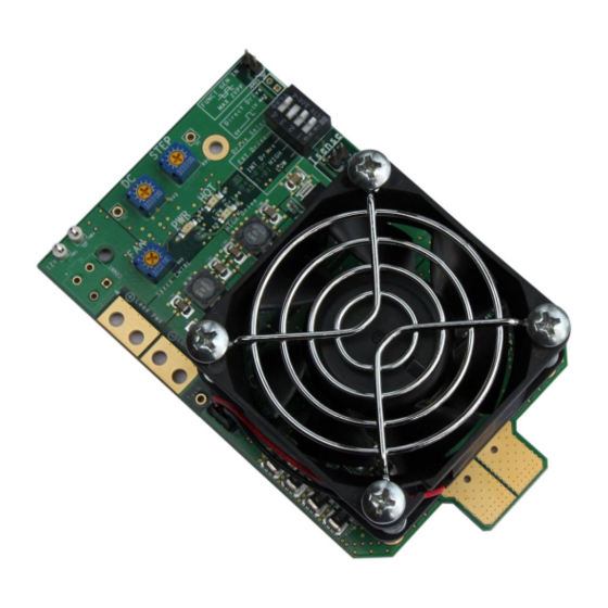
DLT100AGEVB
ON Semiconductor Dynamic
Load Tool Evaluation Board
User's Quick Step Guide
What you will need to use the DLT
•
Multichannel Oscilloscope
•
12 V/600 mA Power Supply with Cables to Connect to
DLT
•
Adjustable Voltage and Switching Frequency Square
Wave (Function) Generator
•
Two Differential Scope Probes or One Differential
Probe and 50 W Terminated Passive Probe
•
Coax Cable to Attach Function Generator to Scope's
External Trigger
•
Small Screwdriver to Adjust Trimmer Pots
© Semiconductor Components Industries, LLC, 2012
April, 2012 − Rev. 0
EVAL BOARD USER'S MANUAL
Attaching the DLT to your circuit
•
Make the Connection to Your Board As Close As
Possible to Where-your Actual Load Will Be Placed
•
Make the Connections to Your Board As Short As
Possible. Any Added Wire Between the DLT and the
Circuit Under Test Will Increase Inductance and
Reduce the di/dt Capability of the DLT
•
Observe the Polarity of the DLT's Connection Tabs
1
http://onsemi.com
Publication Order Number:
EVBUM2101/D
Advertisement
Table of Contents

Related Manuals for ON Semiconductor DLT100AGEVB


Summary of Contents for ON Semiconductor DLT100AGEVB
- Page 1 DLT100AGEVB ON Semiconductor Dynamic Load Tool Evaluation Board User's Quick Step Guide http://onsemi.com EVAL BOARD USER’S MANUAL What you will need to use the DLT Attaching the DLT to your circuit • • Multichannel Oscilloscope Make the Connection to Your Board As Close As •...
- Page 2 DLT100AGEVB Figure 4. Low Current Selected (25 mV/A) Figure 1. DLT Attached with Solder Wick Figure 5. Current Monitor Sense Points Figure 2. DLT Attached to Interposer Supplying Operational Power to the DLT with Header Pins The DLT is powered by an external power supply. It will operate with an input supply of 10 V−18 Vdc.
- Page 3 DLT100AGEVB of the desired load pattern. For example, if the high The oscilloscope can be triggered from the load current power range is used (5 mV/A) and a load step signal, but it is recommended that the external trigger on the between 5 A and 60 A is desired, then the generator function generator be used.
- Page 4 DLT100AGEVB 10. Slowly increase the load by turning the “STEP” external load directly to the board being tested (which is the pot clockwise until you reach the desired load step. best practice) it may be connected directly to the DLT at pins 11.
- Page 5 LIMITATIONS OF LIABILITY: ON Semiconductor shall not be liable for any special, consequential, incidental, indirect or punitive damages, including, but not limited to the costs of requalification, delay, loss of profits or goodwill, arising out of or in connection with the board, even if ON Semiconductor is advised of the possibility of such damages. In no event shall ON Semiconductor’s aggregate liability from any obligation arising out of or in connection with the board, under any theory of liability, exceed the purchase price paid for the board, if any.
Need help?
Do you have a question about the DLT100AGEVB and is the answer not in the manual?
Questions and answers