Advertisement
Quick Links
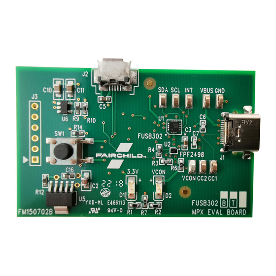
FUSB302GEVB
FUSB302 Type-C]
Interface Detection
Solution Evaluation Board
User's Manual
This user guide supports the evaluation kit for the
FUSB302 It should be used in conjunction with the
FUSB302 data sheets as well as ON Semiconductor's
application notes and technical support team. Please visit
ON Semiconductor's website at www.onsemi.com.
INTRODUCTION
The FUSB302 evaluation board (EVB) and included
software allows customers a complete platform to evaluate
the Type−C interface detection solution the FUSB302
provides. The EVB is designed for both stand−alone
operation and connection to test equipment for specific
testing requirements. The FUSB302 software provides both
fully automatic control and manual control of the FUSB302
functions. With a single connection to a PC and a couple
configurations in the GUI, the EVB can function as a source,
sink or dual−role port.
Description
The FUSB302 targets system designers looking to
implement a DRP/DFP/UFP USB Type−C connector with
low amount of programmability.
The FUSB302 does the USB Type−C detection including
attach, and orientation. The FUSB302 integrates the
physical layer of the USB BMC Power Delivery (PD)
protocol to allow up to 100 W of power and role swap. The
BMC PD block enables full support for alternative
interfaces of the Type−C specification.
Features
•
Dual−Role functionality:
Autonomous DRP toggle
♦
Ability to automatically connect as either a source or
♦
a sink based on what has been attached
Software configurable as a dedicated source,
♦
dedicated sink, or dual−role
Dedicated devices can operate both on a
♦
Type−C receptacle or a Type−C plug with a fixed CC
and VCONN channel
•
Full Type−C 1.3 support. Integrates the following
functionality of the CC pin:
Attach/detach detection as source
♦
Current capability indication as source
♦
Current capability detection as sink
♦
Audio adapter accessory mode
♦
Debug accessory mode
♦
© Semiconductor Components Industries, LLC, 2015
February, 2018 − Rev. 3
EVAL BOARD USER'S MANUAL
Active cable detection
♦
•
Integrates CCx to VCONN switch with over−current
limiting for powering USB3.1 full featured cables
•
USB PD 3.0 support
Automatic GoodCRC packet response
♦
Automatic retries of sending a packet if a GoodCRC
♦
is not received
Automatic soft reset packet sent with retries if
♦
needed
Automatic hard reset ordered set sent
♦
Support for extended/chunked messages
♦
Programmable Power Supply (PPS) support
♦
Basic source−side collision avoidance
♦
•
Package 9−ball WLCSP (1.215 × 1.260 mm)
POWER CONFIGURATION
The FUSB302 EVB is designed to be able to be powered
from a PC connection or powered externally based on the
testing requirements.
Power Supplied from Board
The FUSB302 can fully operate from the VBUS input of
the micro−B USB receptacle J2. To operate the EVB, the
USB power should be provided to the board over the
micro−B USB. Then, the on board regulator generates VDD,
which is 3.3V for device supply. Once valid USB power is
provided, the indicator LED, 3.3V, will be turned on.
2
I
C Communication
Communication with the FUSB302 is done through I
accesses. The EVB allows different ways of connecting I
masters to the FUSB302.
Direct I
C Connection
2
Customers that want to directly connect their I
to the EVB can connect the I
SDA and INT_N test points.
2
PC I
C Connection
The EVB uses a PIC32MX250F128 micro−controller as
an I
C master to control the FUSB302. This is the
2
communication method used by the FUSB302 GUI. By
connecting the PC to the micro−B USB receptacle J2, the
EVB automatically powers the microcontroller and
1
www.onsemi.com
C masters
2
C master signals to the SCL,
2
Publication Order Number:
EVBUM2509/D
C
2
C
2
Advertisement

Related Manuals for ON Semiconductor FUSB302 Type-C


Summary of Contents for ON Semiconductor FUSB302 Type-C
- Page 1 This user guide supports the evaluation kit for the FUSB302 It should be used in conjunction with the EVAL BOARD USER’S MANUAL FUSB302 data sheets as well as ON Semiconductor’s Active cable detection ♦ application notes and technical support team. Please visit •...
-
Page 2: Status Leds
FUSB302GEVB connects the I C master to the FUSB302. The EVB is used by an external I C translator to set the I C levels used automatically generates a regulated 1.8 V supply, U6, which with the FUSB302. Regulator for 1.8V IO Connector Test Points PIC programming... - Page 3 FUSB302GEVB SCHEMATIC Figure 2. FUSB302 EVB FM150702B Schematic (1/2) www.onsemi.com...
- Page 4 FUSB302GEVB Figure 3. FUSB302 EVB FM150702B Schematic (2/2) www.onsemi.com...
-
Page 5: Gui Operation
Program Startup GUI Installation To operate the FUSB302 Evaluation Platform, perform the following steps: Instructions for installing ON Semiconductor FUSB302 1. Install the FUSB302 GUI software as described in Control Software the previous section. 1. Locate and extract the file 2. -
Page 6: Using The Gui
FUSB302GEVB • USING THE GUI “Preferences” There are two basic modes of operation using the Select “Auto Poll” for the GUI to continuously poll ♦ FUSB302 GUI: the FUSB302 for register and log updates • Autonomous operation which uses the “Enable USB •... - Page 7 FUSB302GEVB PD Control as a sink, it displays the source capabilities of the source that The “PD Control” tab logs any PD activity in the USB PD is attached. The user can select different capabilities and Message History window. The log file can be expanded or make the requests.
- Page 8 FUSB302GEVB State Logs To support debug efforts, the “Set State” button can be Events can be logged in the software by checking the used to force a specific state machine state. The state can be “Auto Poll” option in the Preferences menu. These logs can selected in the pull down menu to the left of the “Set State”...
- Page 9 FUSB302GEVB Capabilities the charging algorithm that is used to automatically select a The “Capabilities” tab is to set−up PD functionality of the source capability when connected to a source. Note, the EVB. The settings in this tab dictate how the PD state “Read Src Caps”, “Read Sink Caps”, and “Read Settings”...
- Page 10 FUSB302GEVB Register Map Connected ...” or “ No Device” message in the lower left The “Register Map” tab enables reading and writing any corner of the GUI. value to any register in the FUSB302. When performing a The “Register Poll” option tells the GUI to constantly poll register write, the selected register/registers is/are read back the FUSB302 registers and update the register values.
- Page 11 FUSB302GEVB Script Figure 10. Script Tab The “Script” tab enables the use of scripts to configure the The Execute button will run all the lines of the script. FUSB302. Scripts can be added through the GUI using the The Step button will execute the highlighted line. editing window on the left of the tab.
- Page 12 FUSB302GEVB w,0,0x44,1,0x43,0x02; Data2 information to the EVB. Right−clicking on the Sop field w,0,0x44,1,0x43,0xFF; Jam CRC allows you to add SVIDs. Right clicking on an SVID allows w,0,0x44,1,0x43,0x14; EOP you to remove the SVID or add a Mode. Right−clicking on w,0,0x44,1,0x43,0xFE; TXOFF a Mode allows you to remove it.
- Page 13 LIMITATIONS OF LIABILITY: ON Semiconductor shall not be liable for any special, consequential, incidental, indirect or punitive damages, including, but not limited to the costs of requalification, delay, loss of profits or goodwill, arising out of or in connection with the board, even if ON Semiconductor is advised of the possibility of such damages. In no event shall ON Semiconductor’s aggregate liability from any obligation arising out of or in connection with the board, under any theory of liability, exceed the purchase price paid for the board, if any.
Need help?
Do you have a question about the FUSB302 Type-C and is the answer not in the manual?
Questions and answers