
Related Manuals for Cypress PSoC 4100S Plus


Summary of Contents for Cypress PSoC 4100S Plus
- Page 1 CY8CKIT-149 ® PSoC 4100S Plus Prototyping Kit Guide Doc. #: 002-20729 Rev. *E Cypress Semiconductor 198 Champion Court San Jose, CA 95134-1709 Phone (USA): +1.800.858.1810 Phone (Intnl): +1.408.943.2600 www.cypress.com...
- Page 2 A critical component is any component of a device or system whose failure to perform can be reasonably expected to cause the failure of the device or system, or to affect its safety or effectiveness. Cypress is not liable, in whole or in part, and you shall and hereby do release Cypress from any claim, damage, or other liability arising from or related to all Unintended Uses of Cypress products.
-
Page 3: Table Of Contents
Install Software ......................16 Uninstall Software......................19 3. Kit Operation Theory of Operation....................20 Programming and Debugging the Target PSoC 4100S Plus Device......22 3.2.1 Programming Using PSoC Creator ..............22 3.2.2 Debugging Using PSoC Creator ..............24 3.2.3 Programming Using PSoC Programmer ............24 3.2.4 Mass Storage Programming ................24 USB-UART Bridge .....................24... - Page 4 Header Connections ....................38 User and Passive Inputs ...................42 PSoC 4100S Plus Prototyping Kit Schematics ..............50 Bill of Materials ........................51 Programming PSoC 4100S Plus Prototyping Kit Using MiniProg3/KitProg2 ......51 Revision History CY8CKIT-149 PSoC® 4100S Plus Prototyping Kit Guide, Doc. #: 002-20729 Rev. *E...
-
Page 5: Safety Information
Safety Information Regulatory Compliance The CY8CKIT-149 PSoC 4100S Plus Prototyping Kit is intended for use as a development platform for hardware or software in a laboratory environment. The board is an open system design, which does not include a shielded enclosure. This may cause interference to other electrical or electronic devices in close proximity. - Page 6 Handling Boards The CY8CKIT-149 PSoC 4100S Plus Prototyping Kit board is sensitive to ESD. Hold the board only by its edges. After removing the board from its box, place it on a grounded, static-free surface. Use a conductive foam pad if available.
-
Page 7: Introduction
PSoC 4100S Plus Prototyping Kit supports the PSoC 4100S Plus device, delivering a complete system solution for a wide range of embedded applications at a very low cost. The PSoC 4100S Plus device is a true programmable embedded system-on chip, integrating custom digital peripheral ®... -
Page 8: Kit Contents
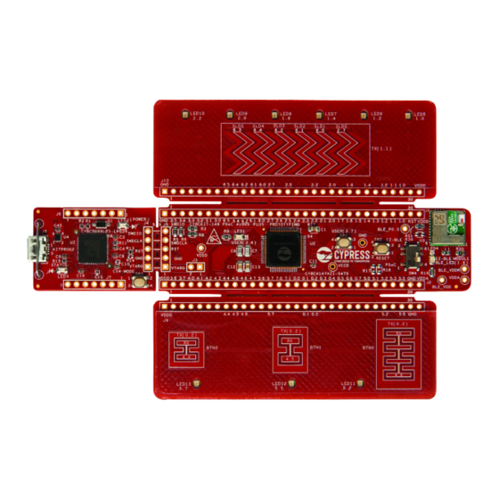
Introduction Kit Contents The PSoC 4100S Plus Prototyping Kit contains a PSoC 4100S Plus Prototyping board and Quick Start Guide. Figure 1-1. CY8CKIT-149 PSoC 4100S Plus Prototyping Kit CY8CKIT-149 PSoC® 4100S Plus Prototyping Kit Guide, Doc. #: 002-20729 Rev. *E... -
Page 9: Psoc Creator
Figure 1-2. PSoC Creator Features PSoC Creator also enables you to tap into an entire tool ecosystem with integrated compiler chains and programmers for PSoC devices. For more information, visit www.cypress.com/psoccreator. Visit the PSoC Creator Video Training Page for video tutorials on learning and using PSoC Creator. -
Page 10: Psoc Creator Code Examples
Introduction 1.2.1 PSoC Creator Code Examples PSoC Creator includes a large number of code examples. These examples are available from the PSoC Creator Start Page, as shown in Figure 1-3 or from the menu File > Code Example..Code examples can speed up your design process by starting you off with a complete design, instead of a blank page. -
Page 11: Kit Code Examples
Introduction Figure 1-4. Code Example Projects with Sample Code 1.2.2 Kit Code Examples You can access the installed kit code examples from the PSoC Creator Start Page. To access these examples, expand Kits under Start; then, expand the specific kit to see the code examples. For a list of code examples that you can use on this kit, see the Code Examples chapter on page 1.2.3... -
Page 12: Component Datasheets
Figure 1-5). Figure 1-5. Opening Component Datasheet Getting Started This guide will help you get acquainted with the PSoC 4100S Plus Prototyping Kit: Software Installation chapter on page 16 describes the installation of the kit software. This ■ includes installation of the PSoC Creator IDE for development and debugging the applications, and PSoC Programmer for programming hex files. -
Page 13: Additional Learning Resources
PSoC Creator. Learning from Peers: Visit community.cypress.com/welcome to meet enthusiastic PSoC develop- ■ ers discussing the next-generation embedded systems on Cypress Developer Community Forums. Technical Support For assistance, visit Cypress Support or contact customer support at +1 (800) 541-4736 Ext. 3 (in the USA) or +1 (408) 943-2600 Ext. -
Page 14: Document Conventions
Introduction Document Conventions Table 1-1. Document Conventions for Guides Convention Usage Courier New Displays file locations, user entered text, and source code: C:\...cd\icc\ Italics Displays file names and reference documentation: Read about the sourcefile.hex file in the PSoC Creator User Guide. [Bracketed, Bold] Displays keyboard commands in procedures: [Enter] or [Ctrl] [C]... -
Page 15: Acronyms
Introduction Acronyms Table 1-2. Acronyms Used in this Document Acronym Description Analog-to-Digital Converter Bridge Control Panel Bluetooth Low Energy Bill of Materials Code Example CMOD Modulator Capacitor Comparator CTANK Shield tank capacitor Digital to Analog Converter DPDT Double-Pole, Double-Throw External Crystal Oscillator Electrostatic Discharge GPIO General Purpose Input/Output... -
Page 16: Software Installation
Software Installation This chapter describes the steps to install the software tools and packages on a PC for using the PSoC 4100S Plus Prototyping Kit. This includes the IDE on which the projects will be built and used for programming. - Page 17 2-1. Figure 2-1. Kit Installer Screen 4. Select the directory in which you want to install the PSoC 4100S Plus Prototyping Kit-related files. Choose the directory and click Next. 5. When you click Next, the PSoC 4100S Plus Prototyping kit installer automatically installs the required software, if it is not present on your PC.
- Page 18 8. Enter your contact information or select the check box Continue Without Contact Information. Click Finish to complete the PSoC 4100S Plus Prototyping kit installation. After the installation is complete, the kit contents are available at the following location: <Install_Directory>\CY8CKIT-149 PSoC 4100S Plus Prototyping Kit...
-
Page 19: Uninstall Software
The software can be uninstalled using one of the following methods: 1. Go to Start > All Programs > Cypress > Cypress Update Manager and select Uninstall. 2. Go to Start > Control Panel > Programs and Features for Windows 7 or Add/Remove Programs for Windows XP and select Uninstall/Change. -
Page 20: Kit Operation
Kit Operation This chapter introduces you to different features of the PSoC 4100S Plus Prototyping Kit. This pri- marily includes the programming and debugging functionalities, KitProg2 USB-UART and USB-I2C bridges, and the procedure to update the KitProg2 firmware. Theory of Operation Figure 3-1 shows the block diagram for the PSoC 4100S Plus Prototyping Kit. - Page 21 Current Measurement Jumper: Using this jumper, you can measure the current consumed by ■ the PSoC 4100S Plus device. This jumper is not populated by default. To use this jumper, you must remove the zero ohm resistor R53. USB 2.0 Micro-B Connector: Using this USB Micro-B connector (J8), you can connect the kit to ■...
-
Page 22: Programming And Debugging The Target Psoc 4100S Plus Device
3-2. The kit enumerates as a composite device. If you are plugging in the PSoC 4100S Plus Prototyping Kit to your PC for the first time, the kit drivers will get installed automatically. The amber status LED (LED3) will turn ON to indicate suc- cessful enumeration. - Page 23 Figure 3-4. This programs the target PSoC 4100S Plus device on the PSoC 4100S Plus Prototyping Kit, and the kit is ready to use. Figure 3-4. Program Device in PSoC Creator CY8CKIT-149 PSoC® 4100S Plus Prototyping Kit Guide, Doc. #: 002-20729 Rev. *E...
-
Page 24: Debugging Using Psoc Creator
The KitProg2 in the CY8CKIT-149 PSoC 4100S Plus Prototyping Kit supports programming through a USB Mass Storage interface. This interface allows you to program the PSoC 4100S Plus device by copying .hex files into an emulated USB Mass Storage device. For more details on using KitProg2 as... -
Page 25: Usb-I2C Bridge
The KitProg2 can function as a USB-I2C bridge and communicate with the software utility Bridge Control Panel (BCP). The I C lines on target PSoC 4100S Plus device are P3[1] (SDA) and P3[0] (SCL), which are hardwired on the board to the I C lines of the KitProg2. -
Page 26: Code Examples
Code Examples This chapter explains the code examples provided along with the PSoC 4100S Plus Prototyping Kit. To access these code examples, download and install the CY8CKIT-149 PSoC 4100S Plus Prototyping Kit setup file from the kit web page: www.cypress.com/CY8CKIT-149. After installation,... - Page 27 Code Examples 5. Make sure switch position of SW4 is on PSoC side. 6. Connect the PSoC 4100S Plus Prototyping kit to the PC using the KitProg2 USB Micro-B connector J8 as described in Programming Using PSoC Creator chapter on page 22 to program the kit with this code example.
- Page 28 Code Examples 9. After the device is acquired, it appears in the tree structure below the KitProg2/<serial num- ber>. Click OK / Connect to exit the window and start programming as shown in Figure 4-5. Figure 4-5. Connect Device from PSoC Creator and Program 10.Code Example Operation: This code example demonstrates the operation of a CapSense linear slider with six segments and three CapSense buttons.
-
Page 29: Using Built-In Psoc Creator Code Examples With The Kit
Using Built-in PSoC Creator Code Examples with the Kit Follow these steps to open and use the built-in PSoC Creator examples. 1. Launch PSoC Creator from Start > All Programs > Cypress > PSoC Creator<version> > PSoC Creator <version>. 2. On the Start page, click Find Code Example... under Start or follow the menu File > Code Example... - Page 30 Code Examples 3. In the Find Code Example window, set the Device family to PSoC 4100S as shown in Figure 4-8. Figure 4-8. Selecting PSoC 4100S Device in Find Code Example Window 4. You can select the CE220891 CapSense with Breathing LED project and see how to use it with the CY8CKIT-149 kit.
- Page 31 Code Examples 6. Open CE220891 CapSense with Breathing LED.pdf from the Workspace Explorer to learn more about the code example and its configuration. See Figure 4-10. Figure 4-10. Project Datasheet: CExxxx CY8CKIT-149 PSoC® 4100S Plus Prototyping Kit Guide, Doc. #: 002-20729 Rev. *E...
-
Page 32: Appendix
Appendix Board Details The PSoC 4100S Plus Prototyping kit consists of the following blocks: PSoC 4100S Plus device (CY8C4147AZI-S475) ■ PSoC 4100S Plus I/O headers J1 and J2 ■ KitProg2 (PSoC 5LP) device (CY8C5868LTI-LP039) ■ KitProg2 I/O headers J6 and J7 ■... - Page 33 Figure A-1. PSoC 4100S Plus Prototyping Kit Pin Details CY8CKIT-149 PSoC® 4100S Plus Prototyping Kit Guide, Doc. #: 002-20729 Rev. *E...
-
Page 34: Hardware Details
A.2.1 Target Board The target board uses the PSoC 4100S Plus device. PSoC 4100S Plus is a scalable and reconfigurable platform architecture for a family of programmable embedded system controllers with an ARM Cortex-M0+ CPU. It combines programmable and reconfigurable digital blocks with flexible automatic routing. -
Page 35: Kitprog2 Board
A.2.2 KitProg2 Board A PSoC 5LP on the KitProg2 board is used to program and debug the target PSoC 4100S Plus device. The KitProg2 PSoC 5LP connects to the USB port of the PC through the USB 2.0 Micro-B connector and to the SWD interface of the target PSoC 4100S Plus device. -
Page 36: Power Supply System
Follow these steps to measure the current consumption of the PSoC 4100S Plus device: 1. Remove the resistor R53 and install a 2-pin jumper in the supplied holes of J3. 2. Connect an ammeter across the 2-pin jumper to measure the current to the PSoC 4100S Plus device. -
Page 37: Board Separation (Snapping)
A.2.4 Board Separation (Snapping) The PSoC 4100S Plus Prototyping Kit consists of a PSoC 4100S Plus and a KitProg2 board. To sep- arate the two boards for evaluation or development, break the two boards apart at the built-in perfo- rated edge between J4 and J5. -
Page 38: Header Connections
The target PSoC 4100S Plus board contains two single inline headers (J1 and J2). These headers are both 1×30-pin headers and include all of the I/Os available on the PSoC 4100S Plus device. These headers support all of the available ports, GND, VDDD, VDDA, and connections to passive elements and user-input devices. - Page 39 Table A-1. J1 Header Pin Details Table A-2. J2 Header Pin Details PSoC 4100S Plus Prototyping kit GPIO Header PSoC 4100S Plus Prototyping kit GPIO Header Signal Description Signal Description J1_01 Ground J2_01 VDDD POWER J1_02 P3_5 GPIO J2_02 P3_6...
- Page 40 The KitProg2 and target boards each contain a 1x5-pin header. These headers provide a physical connection between the two devices. Specifically, the connection includes the SWD interface, required to program/debug the target PSoC 4100S Plus device and EZ-BLE Module, power, ground, and reset.
- Page 41 A.2.5.3 Functionality of J6 and J7 Headers (KitProg2) The KitProg2 board contains two single inline headers (J6 and J7). Both are 1x7-pin-headers, used to pull out several pins of the PSoC 5LP to support advanced features like a low-speed oscilloscope and a low-speed digital logic analyzer.
-
Page 42: User And Passive Inputs
User Switch The target PSoC 4100S Plus board contains a switch connected to the P3[7] pin on the PSoC 4100S Plus device. This switch can be used for general user inputs or to control different states in an application. Figure A-9. User Switch on the Board... - Page 43 A.2.6.2 Reset Switch When the Reset button is pressed, the XRES line of the PSoC 4100S Plus device is pulled to ground, which resets the target device. Figure A-10. Reset (RST) Switch A.2.6.3 Mode Switch (KitProg2) The KitProg2 board contains a push button connected to P1.2 of the PSoC 5LP. When this button is pressed, it toggles between KitProg2 mode and CMSIS-DAP/Mass Storage Mode.
- Page 44 Three CapSense buttons (BTN0, BTN1, and BTN2) are provided on a breakout board to demonstrate the CapSense button functionality of PSoC 4100S Plus device. All the I/Os used for implementing the CapSense buttons are exposed through the headers J2 and J9. Shield for button is connected to ground by default.
- Page 45 A 6-segment linear slider (SLD0, SLD1, SLD2, SLD3, SLD4, and SLD5) is provided on a breakout board to demonstrate the CapSense slider functionality of PSoC 4100S Plus device. All the I/Os used for implementing the CapSense Slider are exposed through the headers J1 and J10. Shield for slider is connected to ground by default.
- Page 46 KitProg2 status LED, see the KitProg2 User Guide. The blue LED (LED1): This is the user LED connected to P3[4] of the target PSoC 4100S Plus ■ device. One blue LED, LED4 (EZ-BLE User): This is the user LED connected to GPIO of EZ-BLE Mod- ■...
- Page 47 Figure A-16. User LED Figure A-17. Feedback LEDs for CapSense Button Figure A-18. Feedback LEDs for CapSense Slider CY8CKIT-149 PSoC® 4100S Plus Prototyping Kit Guide, Doc. #: 002-20729 Rev. *E...
- Page 48 Four CapSense capacitors (CMOD, CSH, CintA, CintB): Required for CapSense functionality of ■ PSoC 4100S Plus device. SAR bypass capacitor for PSoC 4100S Plus device (C1 - Loaded by default). To use port P1.7 as ■ GPIO desolder C1. Two biasing capacitors (C18 and C19 (No Load)): Required to interface an external 32.768 kHz ■...
- Page 49 The board includes an EZ-BLE Module, which is loaded by default. The EZ-BLE Module is a fully integrated, 10 × 10 × 1.8 mm, fully certified, programmable module designed for ease-of-use and reduced time-to-market. It contains Cypress' BLE chip, two crystals, chip antenna, shield, and pas- sive components. For more details, see AN96841 - Getting Started With EZ-BLE Module.
-
Page 50: Psoc 4100S Plus Prototyping Kit Schematics
BLE LED P4_1 P3_7 User Button Use DPDT switch SW4 to switch the SWD connections between PSoC 4100S Plus or EZ-BLE Module as shown in Figure A-21. Figure A-21. DPDT Switch SW4 to Select between PSoC 4100S Plus and EZ-BLE... -
Page 51: Bill Of Materials
Programming PSoC 4100S Plus Prototyping Kit Using MiniProg3/ KitProg2 The target board provides a provision to program the PSoC 4100S Plus device using MiniProg3 or an external KitProg2 via the 5-pin SWD header. To do this, connect wires or a 5-pin 100-mil spaced header to J5. -
Page 52: Revision History
Updated “Install Software” on page Updated Figure 2-2. Updated Kit Operation chapter on page Updated “Programming and Debugging the Target PSoC 4100S Plus Device” on page Updated “Programming Using PSoC Creator” on page Updated Figure 3-2. Updated “USB-UART Bridge” on page... - Page 53 Updated Appendix chapter on page Updated “Hardware Details” on page Updated “Power Supply System” on page Updated “Measure PSoC 4100S Plus Device Current Consumption” on page Updated description. CY8CKIT-149 PSoC® 4100S Plus Prototyping Kit Guide, Doc. #: 002-20729 Rev. *E...
Need help?
Do you have a question about the PSoC 4100S Plus and is the answer not in the manual?
Questions and answers