Advertisement
Quick Links
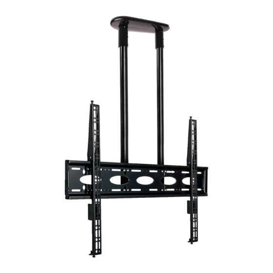
BT8448
UNIVERSAL EXTRA-LARGE
flat screen CEILING MOUNT
INSTALLATION GUIDE
SPECIFICATIONS
• Recommended screen size 65" to 120"
• Max load 130kg (286lbs)
• Suitable for displays with VESA® and non-VESA
fixings up to 1000 x 600mm
• Integrated cable management
• Simple hook-on installation, all mounting
hardware included
www.btechavmounts.com
Advertisement

Related Manuals for B-Tech BT8448


Summary of Contents for B-Tech BT8448
- Page 1 BT8448 UNIVERSAL EXTRA-LARGE flat screen CEILING MOUNT INSTALLATION GUIDE SPECIFICATIONS • Recommended screen size 65" to 120" • Max load 130kg (286lbs) • Suitable for displays with VESA® and non-VESA fixings up to 1000 x 600mm • Integrated cable management •...
-
Page 2: Table Of Contents
Please check carefully to make sure there are no missing or defective parts - defective parts must never be used. B-Tech AV Mounts, its distributors and dealers are not liable or responsible for damage or injury caused by improper installation, improper use or failure to observe these safety instructions. In such cases, all guarantees will expire. -
Page 4: Parts List
BT8448 PARTS LIST PLEASE KEEP THIS FOR FUTURE REFERENCE... - Page 5 Part Name TWIN POLE MOUNT COVER PLATE HALF M8 x 6mm GRUB SCREW M8 x 60mm SCREW M8 x 12mm SCREW Ø50mm POLE POLE END RING Ø50mm COLLAR COLLAR COVER HALF M8 x 15mm GRUB SCREWS M8 x 12mm SCREW M8 SPRING WASHER M8 x 65mm SAFETY BOLT INTERFACE PLATE...
-
Page 6: Installation Instructions
INSTALLATION INSTRUCTIONS FIX CEILING MOUNT Mark and drill holes on ceiling and fix item 1 to the ceiling using items A1, A2 & A3. 010.5mm 276mm HOLES CEILING 120mm 120mm 156mm 396mm CEILING MOUNTED CABLE MANAGEMENT HOLE ATTACH POLES TO CEILING PLATE i. - Page 7 ii. Tighten items 3 on item 1. CEILING NOTE The angle of the pole can be adjusted using item 3 and item 16. WARNING Ensure item 4 or item 5 is in place before any AV equipment is fitted ATTACH COVERPLATES Fix together item 2 over item 1.
- Page 8 MOUNT INTERFACE PLATE TO POLES i. Attach item 14 to item 8 using items 11 & 12. Note: Ensure item 10 are positioned on the back of item 8. ii. Slide item 8 & 14 onto item 6. iii. Once positioned on item 6, tighten item 10 on the back of item 8. iv.
- Page 9 ATTACH INTERFACE ARMS TO SCREEN Attach item 15 to the rear of the screen using the interface kit provided. Note: Ensure interface arms are positioned the correct way round and the same holes are used on both arms. SCREEN REAR OF SCREEN Note: Use spacers on recessed screens and to add extra space for cables RETRACT LOCKING PIECE ON INTERFACE ARMS TO OPEN POSITION...
- Page 10 HOOK SCREEN ONTO INTERFACE PLATE Hook screen onto item 14. Pull down both pull strings on item 15 to lock arms onto wall plate (pull down to release lock). SCREEN PULL STRING SCREEN ADJUSTMENT Optional Feature Level the screen by adjusting the height For extra security (and to stop the adjustment screws on top item 15.
-
Page 11: Product Dimensions
MAX 1000mm TOP VIEW SIDE VIEW BT8448-200 1070mm 426mm BT8448-150 120mm BT8448-100 Ø45mm 156mm Ø10.5mm 276mm THESE INSTRUCTIONS ARE INTENDED AS A GUIDE ONLY AND B-TECH ACCEPTS NO LIABILITY FOR THE ACCURACY 145.9mm OF THE INFORMATION CONTAINED IN THIS DOCUMENT. -
Page 12: B-Tech Contact Details
©2020 B-Tech AV Mounts. All rights reserved. B-Tech AV Mounts is a division of B-Tech International Design and Manufacturing Ltd. B-Tech AV Mounts and the B-Tech logo are registered trade marks. All other brands and product names are trademarks of their respective owners.
Need help?
Do you have a question about the BT8448 and is the answer not in the manual?
Questions and answers