Table of Contents
Advertisement
Quick Links
THANK YOU
Thank you for purchasing the L2 Series lectern. Please read these instructions thoroughly before
installing or assembling this product.
PRODUCT FEATURES
• The only budget-friendly lectern solution that delivers support and security for AV systems,
complete with a patent-pending rack, power, thermal and cable management, and connectivity
• The 12RU removable rack boasts a tool-less experience with easy access to rear connections or
removal for simple servicing, yet locks in place for transportation
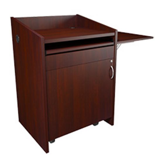
• Flip-up side shelf for extra surface space on certain models
Instruction Sheet
L2 SERIES
Lectern
NOTE: L2 lectern
shown with a
flip-up side shelf
configuration.
I-00824
Rev -
Advertisement
Table of Contents

Subscribe to Our Youtube Channel
Related Manuals for Middle Atlantic Products L2 Series


Summary of Contents for Middle Atlantic Products L2 Series
- Page 1 THANK YOU Thank you for purchasing the L2 Series lectern. Please read these instructions thoroughly before installing or assembling this product. PRODUCT FEATURES • The only budget-friendly lectern solution that delivers support and security for AV systems, complete with a patent-pending rack, power, thermal and cable management, and connectivity •...
-
Page 2: Important Safety Instructions
IMPORTANT SAFETY INSTRUCTIONS • Read these instructions. • Heed all warnings. • Clean only with dry cloth. • Keep these instructions. • Follow all instructions. • Only use attachments/accessories specified by the manufacturer. DANGER HAZARDOUS VOLTAGE: The lightning flash with the arrowhead symbol, within an equilateral triangle is intended to alert the user to the presence of uninsulated dangerous voltage within the product’s enclosure that may be of sufficient magnitude to constitute a risk of electric shock to persons. -
Page 3: Instructions Importantes Sur La Sécurité
INSTRUCTIONS IMPORTANTES SUR LA SÉCURITÉ • Lire ces instructions. • Respectez tous les avertissements. • Nettoyer uniquement avec un chiffon sec. • Conservez ces instructions. • Suivez toutes les instructions. • N'utilisez que des accessoires spécifiés par le fabricant. DANGER TENSION DANGEREUSE: Le symbole de la pointe de flèche, dans un triangle équilatéral, est destiné à alerter l'utilisateur sur la présence de tension dangereuse non isolée dans l'enceinte du produit qui peut être d'une ampleur suffisante pour constituer un risque d'électrocu- tion. -
Page 4: Weight Ratings
WEIGHT RATINGS Model Number Weight Rating Rack Inside L2 Lectern 75 lbs. Maximum Total Rated Load Flip-Up Side Shelf 20 lbs. Maximum Total Rated Load Lectern, Rack, and Flip-Up Side Shelf 150 lbs. Maximum Total Rated Load WARNING: This product is intended for use only with the products and maximum weights indicated. Use with other products or products heavier than the maximum weights indicated may result in instability causing possible injury. - Page 5 SUPPLIED COMPONENTS AND HARDWARE FLIP-UP SIDE SHELF (IF ORDERED) (6x) 8-32 x 1” Side Shelf T-nuts Brackets (6x) (6x) 8-32 x 1 1/4” L2 Lectern #8 Wood Side Shelf Machine Screw HDMI Cable Screw (6’ Length) POWER STRIP Power Cable Power Strip (10’...
- Page 6 PRODUCT FEATURES (CONTINUED) Flip-Up Side Shelf (May be installed on either side of lectern.) Desktop Power Center (WSC320-S, may be installed in either top grommet hole.) Offset Lacer Bar on Back of Lectern NOTE: Door removed for clarity. Lacer Bar on Back of Rack Power Strip Fan With Thermostatic Control...
-
Page 7: Relocating The Rack
REMOVING THE RACK FROM THE GUIDE BRACKETS 1. Remove (2x) thumb screws. (FIGURE A) 2. Use handle on front of lower rack to pull the framework out of the lectern and off the guide brackets. 3. Reverse the procedure to re-install the rack. NOTE: Carefully review all other topics in these instructions before loading equipment in the rack, performing cable management, and re-installing the rack inside the lectern. - Page 8 INSTALLING THE FLIP-UP SIDE SHELF Use the following topic if your lectern configuration includes a flip-up side shelf. 1. Locate pilot mounting holes on the inside of the lectern on the side you wish to install the shelf. (FIGURE C) NOTE: The figure shows a right panel shelf installation, but the procedure is typical for either side.
- Page 9 CONNECTING THE POWER STRIP TO A POWER SOURCE The lectern comes with a power strip pre-installed in the right (facing) position; however, you must connect the power cord to your desired power source. 1. The power cable (G) should already be plugged into the receptacle on the power strip (H) and secured in place with the power cable retainer.
- Page 10 RELOCATING THE POWER STRIP The lectern comes with a power strip pre-installed in the right (facing) position; however, it may be moved to the left position, if desired. 1. Remove the power cable (G) from the power strip (H). 2. Pull the power strip (H) from the power mounting clips. (FIGURE G) NOTE: Different IEC cables may be used;...
- Page 11 INSTALLING THE DESKTOP POWER CENTER (WSC320-S) 1. Decide which lectern top grommet hole you wish to Lectern Top Grommets install the desktop power center in and remove that grommet from the lectern. (FIGURE J) FIGURE J 2. Press tabs on rear of power unit (J) to remove it from the mounting plate (K).
- Page 12 INSTALLING THE DESKTOP POWER CENTER (WSC320-S, CONTINUED) 4. Tighten (2x) screws on the hole mount (L) to secure the assembly to the top grommet hole as shown. (FIGURE M) Tighten (2x) Screws FIGURE M 5. Run the power unit’s (J) power cable through the top grommet hole and connect it to the power strip (H). Hook the front slots on the power unit (J) to the clips on the mounting plate (K) as shown.
- Page 13 INSTALLING THE DESKTOP POWER CENTER (WSC320-S, CONTINUED) 6. Insert 2 tabs on the back of the power unit (J) into the slots on the back of the mounting plate (K) until it clicks into place. (FIGURE P) Tabs on Back of Power Unit Slots on Back of Mounting Plate...
- Page 14 WIRING THE PRE-INSTALLED FAN (CONTINUED) 3. Run the cable from the fan to the inline fan controller (N). (Inputs 1 and 2 are interchangeable.) (FIGURE T) 4. Connect the fan controller power supply (R) to the input on inline fan controller (N). 5.
- Page 15 RELOCATING THE LACER BAR INSIDE THE BACK OF THE LECTERN If desired, you may relocate the lacer bar that is pre-installed inside the back of the lectern into any of the pre-drilled screw locations. (FIGURE V) NOTE: Leaving the lacer bar in the pre-installed top position is best for forming a proper service loop as shown in the next topic.
-
Page 16: Cable Management
CABLE MANAGEMENT This topic shows you how to create a proper service loop when running cables to equipment installed in the rack inside your lectern. 1. Load your equipment into the rack and form a service loop by using wire ties (S) to attach the cables to the lacer bars on the back of the rack and lectern as shown. -
Page 17: Warranty
Voice: 613-836-2501 - Fax: 613-836-2690 / ca.middleatlantic.com - customerservicecanada@middleatlantic.ca Factory Distribution USA: NJ - CA - IL Canada: ON - BC At Middle Atlantic Products we are always listening. Your comments are welcome. Middle Atlantic Products is an ISO 9001 and ISO 14001 Registered Company. Page 17...
Need help?
Do you have a question about the L2 Series and is the answer not in the manual?
Questions and answers