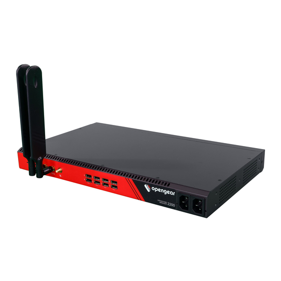
Opengear OM2200 Series User Manual

Opengear OM2200 Series User Manual

Operations manager
Hide thumbs Also See for OM2200 Series:

Advertisement

Operations Manager
User Guide
20.Q4 November 2020

Advertisement

Table of Contents
loading

Summary of Contents for Opengear OM2200 Series

  • Page 1 Operations Manager User Guide 20.Q4 November 2020...
  • Page 2: Table Of Contents

    Contents Copyright © Safety & FCC Statement About This User Guide Installation And Connection Power Connection Connecting to the Network Serial Connection Cellular Connectivity Reset and Erase Initial System Configuration Default Settings Management Console Connection via CLI Change the Root Password Disable a Root User MONITOR Menu System Log...
  • Page 3 CONFIGURE Menu Serial Ports Local Management Consoles Lighthouse Enrollment Playbooks PDUs SNMP Alerts Network Connections Network Interfaces Dual SIM Network Aggregates - Bonds and Bridges Spanning Tree Protocol IPsec Tunnels Network Resilience OOB Failover IP Passthrough User Management Groups Local Users Remote Authentication RemoteLocal for AAA Server Services...
  • Page 4 Session Settings Firewall Firewall Management Interzone Polices Services - Firewall Date & Time Time Zone Manual Settings Automatic Settings System Administration Factory Reset Reboot System Upgrade SNMP SNMP Service SNMP Alert Managers Multiple SNMP Alert Managers Advanced Options Communicating With The Cellular Modem OGCLI Docker Cron...
  • Page 5: Copyright

    “as is,” without warranty of any kind, expressed or implied, including, but not limited to, the implied warranties of fitness or merchantability for a particular purpose. Opengear may make improvements and/or changes in this manual or in the product (s) and/or the program(s) described in this manual at any time. This product could include technical inaccuracies or typographical errors.
  • Page 6: Safety & Fcc Statement

    Do not remove the metal covers. There are no operator serviceable com- ponents inside. Opening or removing the cover may expose you to dangerous voltage which may cause fire or electric shock. Refer all service to Opengear qualified personnel. To avoid electric shock the power cord protective grounding conductor must be connected through to ground.
  • Page 7 This device is not approved for use as a life-support or medical system. Any changes or modifications made to this device without the explicit approval or consent of Opengear will void Opengear of any liability or responsibility of injury or loss caused by any malfunction.
  • Page 8: About This User Guide

    About This User Guide This user guide covers the Opengear Operation Manager products, including the OM2200 family of rack-mountable appliances (available with combinations of up to 48 serial ports and 24 Ethernet ports) and the OM1200 family of small form-factor appliances (available with combinations up to 8 serial and 8 Ethernet ports).
  • Page 9: Installation And Connection

    Installation And Connection This section describes how to install the appliance hardware and connect it to con- trolled devices. INSTALLATION AND CONNECTION...
  • Page 10: Power Connection

    Power Connection The rack mountable units (OM2200) may be equipped with built-in single- or dual- AC or DC power supplies. The small form-factor units (OM1200) use a single external 12V power adapter. OM2200 have dual universal AC power supplies with auto failover built in. These power supplies each accept AC input voltage between 100 and 240 VAC with a fre- quency of 50 or 60 Hz.
  • Page 11: Connecting To The Network

    Connecting to the Network All Operations Manager products have two network connections labeled NET1 and NET2. In the OM2200, there are options for copper wiring (on a standard RJ-45 con- nector) and fiber (through a standard SFP module). The network connections on the OM2200 are located on the serial port side of the unit.
  • Page 12: Serial Connection

    Serial Connection The serial connections feature RS-232 with software selectable pin outs (Cisco straight –X2 or Cisco reversed –X1). Connect serial devices with the appropriate STP cables. INSTALLATION AND CONNECTION...
  • Page 13: Cellular Connectivity

    Cellular Connectivity The Operations Manager products offer an optional global cellular LTE interface (models with -L suffix). The cellular interface is certified for global deployments with most carriers and provides a CAT12 LTE interface supporting most frequencies in use. To activate the cellular interface, you should contact your local cellular carrier and activate a data plan associated to the SIM installed.
  • Page 14: Reset And Erase

    Reset and Erase CONFIGURE > System > Reboot The OPERATIONS MANAGER reboots with all settings (e.g. the assigned network IP address) preserved. To reboot the unit: Select CONFIGURE > System > Reboot. To erase the unit: Push the Erase button on the port-side panel twice with a bent paper clip while the unit is powered on.
  • Page 15: Initial System Configuration

    Initial System Configuration This section provides step-by-step instructions for the initial configuration of your OPERATIONS MANAGER. By default, all interfaces are enabled. The unit can be managed via WebGUI or by command line interface (CLI). "Default Settings" on the next page "Management Console Connection via CLI"...
  • Page 16: Default Settings

    Default Settings The OPERATIONS MANAGER comes configured with a default static IP Address of 192.168.0.1 Subnet Mask 255.255.255.0. The OM offers a WebGUI via web browser that supports HTML5. 1. Type https://192.168.0.1 in the address bar. HTTPS is enabled by default. 2.
  • Page 17 4. Next, you will be presented with the ACCESS > Serial Ports page that shows you a list of serial devices and links to a Web Terminal or SSH connection for each. Using the WebUI The WebUI can switched between Light or Dark mode by adjusting the toggle on the bottom left.
  • Page 18 The Help menu contains a link to generate a Technical Support Reportt that can be used by Opengear Support for troubleshooting. It also contains a link to the latest Operations Manager User Manual. The System menu presents the Current version, REST API version, Hostname, Serial Number, Model, and Current user.
  • Page 19: Management Console Connection Via Cli

    Management Console Connection via CLI The Command Line Interface (CLI) is accessible using your preferred application to establish an SSH session. 1. Input the default IP Address of 192.168.0.1. SSH port 22 is enabled by default. 2. When prompted, enter the log in and password in the CLI 3.
  • Page 20: Change The Root Password

    Change the Root Password CONFIGURE > User Management > Local Users For security reasons, only the root user can initially log into the appliance. Upon ini- tial log in the default password must be changed. To change the password at any time, 1.
  • Page 21 3. Enter a new password in the Password field and enter it again in the Con- firm Password field. 4. Click Save User. INITIAL SYSTEM CONFIGURATION...
  • Page 22: Disable A Root User

    Disable a Root User CONFIGURE > User management > Local Users To disable a root user: Note: Before proceeding, make sure that another user exists that has the Administrator role or is in a group with the Administrator role. For information on creating, editing, and deleting users, see "Local Users"...
  • Page 23 1. Click CONFIGURE > Network Connections > Network Interfaces 2. Click the expand arrow to the right of the desired interface to view its details. 3. Click the plus icon to open the New Connection page. INITIAL SYSTEM CONFIGURATION...
  • Page 24 4. Select the Interface and Connection Type for your new connection. 5. The form on the bottom part of the page will change based on the Con- nection Type you choose. Enter the necessary information and click Apply. To disable or delete interfaces, use the controls on the expanded section on the CONFIGURE >...
  • Page 25 3. Click Enabled Automatic. 4. Change the Media Setting as needed and click Apply. INITIAL SYSTEM CONFIGURATION...
  • Page 26: Monitor Menu

    MONITOR Menu The MONITOR Menu is a relatively short section comprising only three topics. System Log Details of the system activity log, access and communications events with the server and with attached serial, network and power devices. LLDP/CDP Neighbors Details of the LLDP/CDP Neighbors that are displayed when enabled for a connection.
  • Page 27: System Log

    System Log MONITOR > System Log The OPERATIONS MANAGER maintains a log of system activity, access and com- munications events with the server and with attached serial, network and power devices. To view the System Log, click MONITOR > System Log. The System Log page lets you change the Number of Log Lines displayed on the screen.
  • Page 28: Lldp Cdp Neighbors

    LLDP CDP Neighbors MONITOR > LLDP/CDP Neighbors The OPERATIONS MANAGER displays LLDP/CDP Neighbors when enabled for a connection. See CONFIGURE > SERVICES > Network Discovery Protocols to enable/disable. MONITOR MENU...
  • Page 29: Triggered Playbooks

    Triggered Playbooks MONITOR > Triggered Playbooks For information on creating Playbooks, see Playbooks. To monitor current Playbooks, click on Monitor > Playbooks. Choose the time period if desired, and filter by Name of Playlist to view any that have been triggered.
  • Page 30: Access Menu

    ACCESS Menu The ACCESS menu lets you access the OPERATIONS MANAGER via a built-in Web Terminal. It also provides SSH and Web Terminal access to specific ports.  ACCESS MENU...
  • Page 31: Local Terminal

    Local Terminal ACCESS > Local Terminal The OPERATIONS MANAGER includes a web-based terminal. To access this bash shell instance: 1. Select ACCESS > Local Terminal. 2. At the log in prompt, enter a username and press Return. 3. At the password prompt, enter a password and press Return. 4.
  • Page 32: Access Serial Ports

    Access Serial Ports ACCESS > Serial Ports The ACCESS > Serial Ports page allows you to quickly locate and access specific ports via Web Terminal or SSH. Click the expand arrow to the right of the port to see these options. Quick Search To find a specific port by its port label, use the Quick Search form on the top of the ACCESS >...
  • Page 33 1. Locate the particular port on the ACCESS > Serial Ports page and click the expand arrow. 2. Click the Web Terminal or SSH link for the particular port. Choosing Web Terminal opens a new browser tab with the terminal. Choosing SSH opens an application you have previously associated with SSH connections from your browser.
  • Page 34 ACCESS MENU...
  • Page 35: Configure Menu

    CONFIGURE Menu This section provides step-by-step instructions for the menu items under the CONFIGURE menu. CONFIGURE MENU...
  • Page 36: Serial Ports

    Serial Ports CONFIGURE > Serial Ports Click CONFIGURE > Serial Ports. A list of serial ports appears. This page lets you select serial ports and Autodiscover Selected ports. You can Schedule Autodiscover by clicking the button. This opens a page that allows you to select the ports and specify a time and period for port detection to occur.
  • Page 37 From the Configure > Serial Ports page, click theEdit Serial Port button under Actions next to the Serial Port you wish to configure. The Edit Serial Port page opens. CONFIGURE MENU...
  • Page 38 The Edit Serial Port page lets you configure the serial port’s: Label: This can be used to locate this port using the Quick Search form on the ACCESS > Serial Ports page. Mode: Disabled or Console Server Pin out: X1 Cisco Rolled or X2 Cisco Straight Baud Rate: 50 to 230,400 bps Data Bits: 5, 6, 7, 8 Parity: None, Odd, Even, Mark, Space...
  • Page 39 Logging Levels Serial Port Aliases CONFIGURE MENU...
  • Page 40: Local Management Consoles

    Local Management Consoles CONFIGURE > Local Management Consoles You can edit settings or disable the local RJ45 serial console (Cisco straight -X2 pinout) and the USB serial console (needs user supplied micro-USB to USB-A cable). To edit the settings of a local management console: 1.
  • Page 41 3. The Edit Local Management Console page lets you control: Baud Rate Data Bits Parity Stop Bits Terminal Emulation Enable or disable Kernel Debug Messages Enable or disable the selected Management Console Note: Enabling Kernel Debug Messages can only be applied to a single serial management console.
  • Page 42: Lighthouse Enrollment

    Lighthouse Enrollment CONFIGURE > Lighthouse Enrollment Opengear appliances can be enrolled into a Lighthouse instance, providing cent- ralized access to console ports, NetOps Automation, and central configuration of Opengear devices. To enroll your OPERATIONS MANAGER to a Lighthouse instance, you must have Lighthouse installed and have an enrollment token set in Lighthouse.
  • Page 43 Port and an Enrollment Bundle (see the Lighthouse User Guide more information). 4. Click Apply. Note: Enrollment can also be done directly via Lighthouse using the Add Node function. See the Lighthouse User Guide for more instructions on enrolling Opengear devices into Lighthouse. CONFIGURE MENU...
  • Page 44: Playbooks

    Playbooks CONFIGURE > Playbooks Playbooks are configurable systems that periodically check if a Trigger condition has been met. They can be configured to perform a one or more specified Reaction. To create a new Playbook, select Configure > Playbooks. Click the Plus button to create a new Playbook. CONFIGURE MENU...
  • Page 45 1. Enter a Name for the Playbook. 2. Add a Description. 3. Select Enabled to activate the Playbook after you have created it. 4. Enter an Interval in seconds to control the frequency that the Trigger will be checked. 5. Choose the type of Trigger to use from the Trigger Type drop down. 6.
  • Page 46 Clicking on each Reaction opens a custom screen to provide necessary inform- ation. When you are finished, click Apply. After you have created Playbooks, you can Edit orDelete them from the Configure > Playbooks page. To monitor current Playbooks, click on Monitor > Playbooks. Choose the time period if desired and filter by Name of Playlist to view any that have been triggered.
  • Page 47: Pdus

    PDUs CONFIGURE > PDUs One or more Power Distribution Units (PDUs), both Local and Remote can be mon- itored. To add information for a PDU, select Configure > PDUs. Click the Plus button to configure a new PDU. CONFIGURE MENU...
  • Page 48 1. Enter a Label for this PDU. 2. Select the Monitor checkbox. 3. Choose Local or Remote. 4. Select the appropriate Driver from the drop-down list. 5. Select the Port. 6. Add a Description. 7. Under Access Settings, enter a Username and Password to use when connecting to the device.
  • Page 49: Snmp Alerts

    SNMP Alerts CONFIGURE > SNMP Alerts On the Configure > Alerts page, you can add and delete SNMP alerts. You can set triggers to send SNMP alerts for the following: Authentication: when a user attempts to log in via SSH, REST API, or the device's serial ports.
  • Page 50 System: when the system reboots or the supply bus voltages are out of range. Use the slider to adjust the upper and lower voltage range. Networking: based on the cell signal strength and each interface's link state. Use the slider to adjust the upper and lower signal strength. Configuration: when changes occur to the system configuration.
  • Page 51: Network Connections

    Network Connections CONFIGURE > NETWORK CONNECTIONS The Network Connections menu contains the Network Interfaces and IPsec Tun- nels settings. CONFIGURE MENU...
  • Page 52: Network Interfaces

    Network Interfaces CONFIGURE > NETWORK CONNECTIONS > Network Interfaces The interface supports both IPv4 and IPv6 networks. The IP address of the unit can be setup for Static or DHCP. The following settings can be configured for network ports: IPv4, IPv6 Static and/or DHCP Enabling or disabling network interfaces Ethernet Media types...
  • Page 53: Dual Sim

    Dual SIM CONFIGURE > NETWORK CONNECTIONS> Network Interfaces > Cellular Inter- face (LTE) Devices that carry two SIM cards can have both SIMs configured so that you can manually activate either SIM card slot. Display SIM Status and Signal Strength Note: For information about configuring the Signal Strength Thresholds see: "SNMP Alerts"...
  • Page 54 The signal bar color (not the number of bars) indicates signal strength: Green if signal is above the higher threshold. Orange if signal is between lower and higher threshold. if signal is below the lower threshold, Grey for 0 or not active, 5.
  • Page 55 Note: When the Refresh button is clicked the signal strength is only updated for the active SIM. If you would like to know what the other SIM Signal Strength is, you need to activate it, let the modem come back online, which may take 3 minutes or more.
  • Page 56 Note: During the change-over the current IP address is hidden and then returned when the modem re-connects. 5. If you require, you can monitor the interface during the changeover via the CLI with the command:. watch ip address show dev wwan0 You can also set the SIM settings by expanding the menu for each SIM to set the APN.
  • Page 57: Network Aggregates - Bonds And Bridges

    Network Aggregates - Bonds and Bridges CONFIGURE > NETWORK CONNECTIONS > Network Interfaces > Select the tar- get interface The Network Aggregates feature allows you to create or edit bridges that contain any type of interface or other config options which are included in a bridge or bond after it is created, without having to delete the bridge or bond and start over.
  • Page 58 3. Complete the new bridge details form as in the Bridge Form Definitions definitions table below. 4. Click the Create button to finalize the creation of the new bridge. Edit an Existing Bridge To edit an existing bridge: 1. Navigate to the Configure > Network Connections > Network Interfaces page on the Web UI.
  • Page 59 loops so that there is no broadcast radiation and the network stays healthy and reliable Be able to function with redundant links (intentional network loops) to increase the networks reliability and fault tolerance Network Interface Click the check box of each network interface you want to Selection include in the bridge.
  • Page 60 3. Complete the new bond details form as in the Bond Form Definitions definitions table below. 4. Click the Create button to finalize the creation of the new bond. Network connections from non-primary interfaces will be deleted when the new bond is created. Edit an Existing Bond To edit an existing bond: 1.
  • Page 61 Round Robin Balancing - Packets are sequentially trans- mitted/received through each interfaces one by one. Active Backup - If the active secondary interface is changed during a failover, the bond interface’s MAC address is then changed to match the new active secondary’s MAC address. XOR Balancing - Balances traffic by splitting up outgoing packets between the Ethernet interfaces, using the same one for each specific destination when possible.
  • Page 62 Connections which exist on the Primary Interface will be attached to the Bond/Bridge after it is initially created. When a Bond/Bridge is deleted, any Network Connections which exist on the aggregate interface are handed over to the Primary Interface. Active When the Primary Interface is created, the connections inher- Connections ited by the new bond are listed here.
  • Page 63: Spanning Tree Protocol

    Spanning Tree Protocol CONFIGURE > NETWORK CONNECTIONS > Network Interfaces > Select the tar- get interface Spanning Tree Protocol (STP) allows Operation Manager devices to discover and eliminate loops in network bridge links, preventing broadcast radiation and allow- ing redundancy. When STP is implemented on switches to monitor the network topology, every link between switches, and in particular redundant links, are cataloged.
  • Page 64 Bridge With STP Enabled - UI CONFIGURE > NETWORK CONNECTIONS > Network Interfaces > Select the tar- get interface > New Bridge page 1. In the Network Interfaces page, click the Create New Bridge button. 2. Click to select the Enable Spanning Tree Protocol option. Bridge With STP Enabled - OGCLI admin@om2248:~# ogcli get physif system_net_physifs-5 bridge_setting.id="system_net_physifs-5"...
  • Page 65 Bridge With STP Disabled - OGCLI admin@om2248:~# ogcli update physif system_net_physifs-5 bridge_setting.stp_enabled=false bridge_setting.id="system_net_physifs-5" bridge_setting.stp_enabled=false description="Bridge" device="br0" enabled=true id="system_net_physifs-5" media="bridge" name="init_br0" slaves[0]="net2.3" CONFIGURE MENU...
  • Page 66: Ipsec Tunnels

    IPsec Tunnels CONFIGURE > NETWORK CONNECTIONS > IPsec Tunnels On the IPsec Tunnels page, you can create, edit, and delete IPsec tunnels. To create an IPsec tunnel: 1. Click CONFIGURE > NETWORK CONNECTIONS > IPsec Tunnels. 2. Click CREATE TUNNEL. This opens the EDIT IPSEC TUNNEL page. CONFIGURE MENU...
  • Page 67 3. In the top section of the page, TUNNEL CONFIGURATION, click the Enabled check box and give your new tunnel a name. 4. Select an IKE Protocol Version to use for exchanging keys. IKEv1 provides two modes: Main and Aggressive. When using IKEv1, Main Mode is recom- mended.
  • Page 68 7. Enter an Outer Local Address, a local IP address to use as the source address of the tunnel 8. Enter an Outer Remote Address, the IP address or hostname of the remote end of the tunnel. 9. Scroll down to the Traffic Selectors section of the page. 10.
  • Page 69 12. Enter a PSK Shared Secret. 13. Enter a Local ID and Remote ID. 14. Click Save. The new tunnel is now listed on the CONFIGURE > NETWORK CONNECTIONS > IPsec Tunnels page. CONFIGURE MENU...
  • Page 70: Network Resilience

    Network Resilience CONFIGURE > NETWORK RESILIENCE > Under the NETWORK RESILIENCE menu, you can manage Out-of-Band (OOB) and IP Passthrough settings. CONFIGURE MENU...
  • Page 71: Oob Failover

    OOB Failover CONFIGURE > NETWORK RESILIENCE > OOB Failover To manage Out-of-Band failover, click CONFIGURE > NETWORK RESILIENCE > OOB Failover: CONFIGURE MENU...
  • Page 72: Ip Passthrough

    IP Passthrough CONFIGURE > NETWORK RESILIENCE > IP Passthrough To manage IP Passthrough settings clickCONFIGURE > NETWORK RESILIENCE > OOB Failover: CONFIGURE MENU...
  • Page 73: User Management

    User Management CONFIGURE > USER MANAGEMENT Under the User Management menu, you can create, edit, and delete groups and users, as well as assign users to groups. You can also set up remote user authen- tication. CONFIGURE MENU...
  • Page 74: Groups

    Groups CONFIGURE > USER MANAGEMENT > Groups To create a new group: 1. Select CONFIGURE > USER MANAGEMENT > Groups. 2. Click the Plus button. The NEW GROUP page opens. CONFIGURE MENU...
  • Page 75 3. Enter a Group Name, Description, and select a Role for the group. 4. Choosing the Console User role allows you to select specific ports this group will be able to access. CONFIGURE MENU...
  • Page 76 5. Click the Group Enabled checkbox to enable the group. After creation, groups can also be enabled or disabled from the CONFIGURE > USER MANAGEMENT > Groups page. 6. Click Save Group. Note: Group Name is case sensitive. It can contain numbers and some alpha- numeric characters.
  • Page 77: Local Users

    Local Users CONFIGURE > USER MANAGEMENT > Local Users To create a new user: 1. Navigate to the CONFIGURE > USER MANAGEMENT > Local Users tab. 2. Click the + button. The New User dialog appears. CONFIGURE MENU...
  • Page 78 3. Enter a Username, Description, and Password. 4. Re-enter the Password in the Confirm Password field. 5. Select the Enabled checkbox. 6. Click Apply. To create a new user without password which causes them to fall back to remote authentication: 1.
  • Page 79 8. Select the Enabled checkbox. 9. Click Apply. To modify an existing user: 1. Select CONFIGURE > USER MANAGEMENT > Local Users 2. Click the Edit User button in the Actions section next to the user to be mod- ified and make desired changes. 3.
  • Page 80 1. Select CONFIGURE > USER MANAGEMENT > Local Users 2. Click the Manage SSH Authorized Keys button in the Actions section next to the user. 3. Click the Plus button to add a new key. This opens the NEW AUTHORIZED KEY page for this user. 4.
  • Page 81 6. Click the Delete button next to the key you wish to remove. To delete a user: 1. Select CONFIGURE > USER MANAGEMENT > Local Users 2. Click the Delete User button in the Actions section next to the user to be deleted.
  • Page 82: Remote Authentication

    Remote Authentication CONFIGURE > USER MANAGEMENT > Remote Authentication The OPERATIONS MANAGER supports three AAA systems: LDAP (Active Directory and OpenLDAP) RADIUS TACACS+ To begin, select CONFIGURE > USER MANAGEMENT > Remote Authentication. To configure LDAP authentication (for example): 1. Under CONFIGURE > User Management > Remote Authentication, select LDAP from the Mode drop-down menu.
  • Page 83 2. Add the Address and optionally the Port of the LDAP server to query. 3. Add the Base DN that corresponds to the LDAP system being queried. For example, if a user’s distinguished name is cn=John Doe,d- c=Users,dc=ACME,dc=com, the Base DN is dc=ACME,dc=com 4.
  • Page 84 6. Add the Username Attribute. This depends on the underlying LDAP system. Use sAMAccountName for Active Directory systems, and uid for OpenLDAP based systems. 7. Add the Group Membership Attribute. This is only needed for Active Dir- ectory and is generally memberOf. 8.
  • Page 85 2. Add the Address and optionally the Port of the RADIUS authentication server to query. 3. Add the Address and optionally the Port of the RADIUS accounting server to send accounting information to. 4. Add and confirm the Server password, also known as the RADIUS Secret. Note: Multiple servers can be added.
  • Page 86 1. Add the Address and optionally the Port of the TACACS+ authentication server to query. 2. Select the Login Method.  PAP is the default method. However, if the server uses DES-encrypted passwords, select Login. 3. Add and confirm the Server password, also known as the TACACS+ Secret. 4.
  • Page 87 To do this with Cisco ACS, see Setting up permissions with Cisco ACS 5 and TACACS+ on the Opengear Help Desk. CONFIGURE MENU...
  • Page 88: Remotelocal For Aaa Server

    RemoteLocal for AAA Server CONFIGURE > USER MANAGEMENT > Remote Authentication CONFIGURE > USER MANAGEMENT > Local Users RemoteLocal authentication allows users to be authenticated locally if they don't exist on the AAA server so that users can still access any consoles that are required to be accessed.
  • Page 89 1. Navigate to CONFIGURE > USER MANAGEMENT > Remote Authentication. 2. Ensure the required protocol mode is selected (TACACS+, RADIUS, LDAP). 3. Select the authentication policy you require (DownLocal or Local). 4. Click Apply. The policy change is confirmed by a green confirmation banner. Authentication Scenarios The following example shows RADIUS protocol mode, but the behavior is the same for other protocols such as TACACS+ or LDAP.
  • Page 90 Remote Server Down / Unreachable: If the remote AAA server is unreachable or down, the OM device tries to authenticate the user using a local account as per a regular local log in. Remote server is up, but incorrect credentials: The user is denied access.
  • Page 91: Services

    Services CONFIGURE > SERVICES The CONFIGURE > SERVICES menu lets you manage services that work with the OPERATIONS MANAGER. CONFIGURE MENU...
  • Page 92: Https Certificate

    HTTPS Certificate CONFIGURE > SERVICES > HTTPS Certificate The OPERATIONS MANAGER ships with a private SSL Certificate that encrypts communications between it and the browser. To examine this certificate or generate a new Certificate Signing Request, select CONFIGURE > SERVICES > HTTPS Certificate. The details of the Current SSL Certificate appear.
  • Page 93 CONFIGURE MENU...
  • Page 94: Network Discovery Protocols

    Network Discovery Protocols CONFIGURE > SERVICES > Network Discovery Protocols The OPERATIONS MANAGER displays LLDP/CDP Neighbors when enabled for a connection. See CONFIGURE > SERVICES > Network Discovery Protocols to enable/disable. The CONFIGURE > SERVICES > Network Discovery Protocols > LLDP/CDP NEIGHBORS page allows you to enable this service by clicking the Enable check- box.
  • Page 95: Routing

    Routing CONFIGURE > SERVICES > Routing You can enable routing protocols on this page. Select CONFIGURE > SERVICES > Routing page. Select any of the following and click the Apply button: BGP (Border Gateway Protocol) OSPF (Open Shortest Path First Protocol) IS-IS (Intermediate System to System Protocol) RIPD (Routing Information Protocol) CONFIGURE MENU...
  • Page 96: Ssh

    CONFIGURE > SERVICES > SSH To modify the port used for connecting to serial consoles via SSH, click CONFIGURE > SERVICES > SSH. This page also lets you set the delimiting character used to separate the username with port selection information. The default delimiter is a plus sign (+). For example, username+port@address.
  • Page 97 increases linearly until the unauthenticated connections reach full. Max Startups Full is the number of unauthenticated connections allowed. CONFIGURE MENU...
  • Page 98: Unauthenticated Ssh To Console Ports

    Usually, you would need to authenticate on the Opengear appliance, followed by any log in to a device you are connecting to via the serial port.
  • Page 99 Enable SSH Note: This feature may be enabled using the default settings without the need for configuration. 1. Open the SSH form, Configure > Services > SSH > SSH (form). 2. Complete the SSH form (if this is the first time Unauthenticated SSH has been used), a description of the input data is provided at Properties and Settings in this topic.
  • Page 100 In this example, the SSH base port is TCP port 3000, so SSH to TCP port 3001 directly con- ber. nects you to serial port 1 SSH to the Opengear device, log in adding :portXX to your username (e.g. root:port01 or operator:port01)
  • Page 101 Note: For additional reading on connecting to serial ports see: https://opengear.zendesk.com/hc/en-us/articles/216373543-Communicating- with-serial-port-connected-devices Note: Serial ports in the Local Console and Disabled ports modes are not available for SSH connection. Feature Persist If the device has an active console session after closing pmshell, connecting to the device again will resume the session and you are not prompted for the device pass- word.
  • Page 102 delimiter")), Source: validator if (strlen(v) != 1) valid = 0; else if (v[0] == '\'') valid = 0; else if (v[0] == '"') valid = 0; else if (v[0] == '`') valid = 0; else if (v[0] == ' ') valid = 0; // breaks sshd_config else if (v[0] == '=') valid = 0;...
  • Page 103 Max Startups Full The number of connections pending authen- tication before all new connections are refused. Required full: int (minimum = 1; default = 100) Max Startups Rate This is the percentage rate at which new con- nections are refused once the Max Startups value is reached.
  • Page 104: Syslog

    Syslog CONFIGURE > SERVICES > Syslog Administrative users can specify multiple external servers to export the syslog to via TCP or UDP. This page lists any previously added external syslog servers. To add a new one, 1. Navigate to CONFIGURE > SERVICES > Syslog. 2.
  • Page 105 2. Enter the Server Address. 3. Enter the Protocol, either UDP or TCP. 4. Enter the correct Port. If no port is entered, UDP defaults to port 514 and TCP defaults to 601. 5. Click Apply. To edit an existing syslog server, click the Edit button under Actions. Delete a server by clicking the Delete button or the checkbox next to multiple servers and the Delete Selected button.
  • Page 106: Remote Syslog

    Remote Syslog Configure > Services > Syslog Configure > Services > Syslog > Create Syslog Server Configure > Services > Syslog > Edit Syslog Server Configure > Services > Syslog > Global Serial Port Settings Configure > Serial Ports > Edit Serial Port The Remote Syslog facility provides the flexibility to specify a Remote Syslog server so that you can redirect console serial port logs to the Remote Syslog server so as to provide a central (and regional) repository where you can view the port-...
  • Page 107 Set Logging Levels For Remote Syslog Server Local Log Level limits the Syslog information being logged. Any log entry with a value equal or greater than the level specified in the config is sent to the remote server. Ensure Port Logging is Set to the Required Level 1.
  • Page 108 1. In the Configure > Services > Syslog tab click on the IP address of the target server. The Edit Syslog Server tab is opened for editing. 2. You can delete a server by clicking the Delete button at the top right of the Edit tab page.
  • Page 109 Syslog Facility Definitions Facility Definition Kern Kernel messages User User-level messages Mail Mail system Daemon System daemons Auth Security/authentication messages Syslog Messages generated internally by syslogd Line printer subsystem News Network news subsystem uucp UUCP subsystem Cron Clock daemon Authpriv Security/authentication messages FTP daemon Local...
  • Page 110 Syslog Severity Definitions Severity Definition 0- Emergency System is unusable. 1 - Alert Action must be taken immediately. 2 - Critical Critical conditions. 3 - Error Error conditions. 4 - Warning Warning conditions. 5 - Notice Normal but significant conditions. 6 - Info Informational messages 7- Debug...
  • Page 111: Session Settings

    Session Settings SETTINGS > SERVICES > Session Settings To modify Web and CLI session settings navigate to the SETTINGS > Services > Session Settings page. Web Session Timeout: This value can be set from 1 to 1440 minutes. CLI Session Timeout: This value can be set from 1 to 1440 minutes or set it to 0 to disable the timeout.
  • Page 112: Firewall

    Firewall CONFIGURE > FIREWALL The CONFIGURE > FIREWALL menu lets you configure Firewall Management, Interzone Policies, and Services. CONFIGURE MENU...
  • Page 113: Firewall Management

    Firewall Management CONFIGURE > FIREWALL > Management To change firewall management settings navigate to CONFIGURE > FIREWALL > Management. You can expand each zone by clicking the Expand arrow on the right. Once expan- ded, you can click Edit Zone to change settings for a particular zone. CONFIGURE MENU...
  • Page 114 The Edit Zone page has three tabs. The ZONE SETUP page allows you to: Modify the Name of the zone Add a Description for this zone Permit all Traffic Masquerade Traffic Select Physical Interfaces Manage Permitted Services by clicking on Plus or Minus next to each Note: You can use the Filter Interfaces and Filter Available Services text boxes to navigate through the lists.
  • Page 115 The MANAGE PORT FORWARDING tab allows you to add, edit, and delete for- warding rules for the particular zone you are editing. The third tab, MANAGE CUSTOM RULES, allows you to add, edit , and delete cus- tom firewall rules for the zone you are editing. These custom rules continue to exist after reboots, upgrades, and power cycles.
  • Page 116 1. Click Add custom rule. 2. Enter a Description for this rule. 3. Enter Rule Content, custom rule content formatted with firewall-cmd syntax. 4. Click Apply. All rules will be wrapped as follows: firewall-cmd --permanent --zone=lan --add-rich-rule=RULE CONTENT Additional menu options under CONFIGURE > FIREWALL are Rules, Services, and Zones.
  • Page 117 Services can be added, deleted, or edited from this page. Scroll to the bottom of the page to access the Plus button to add a new service. Enter a Service description and a Zone for the new rule. Manage Firewall Zones Click CONFIGURE >...
  • Page 118 Zones can be added, deleted, or edited from this page. Click the PLUS symbol on the top right of the page to add a new zone. CONFIGURE MENU...
  • Page 119 The NEW FIREWALL ZONE page allows you to: Name the zone Add a Description for this zone Permit all Traffic Masquerade Traffic Select Physical Interfaces CONFIGURE MENU...
  • Page 120: Interzone Polices

    Interzone Polices CONFIGURE > FIREWALL > Interzone Policies Click CONFIGURE > FIREWALL > Interzone Policies. This opens the INTERZONE POLICIES. CONFIGURE MENU...
  • Page 121: Services - Firewall

    Services - Firewall CONFIGURE > FIREWALL > Services Managing Firewall Services Click CONFIGURE > FIREWALL > Services. This opens the SERVICES page with a long list of predefined firewall services. Services can be added, deleted, or edited from this page. Note: Predefined services cannot be edited.
  • Page 122 Enter a Name, Label, Port #, and Protocol. Select a Protocol (TCP or UDP) from the Plus button menu. Add more Ports and Protocols as desired and click Apply. CONFIGURE MENU...
  • Page 123: Date & Time

    Date & Time CONFIGURE > DATE & TIME The Date & Time section of the navigation bar provides a means to Set the time zone Manually set the correct time and date Automatically set the date and time CONFIGURE MENU...
  • Page 124: Time Zone

    Time Zone CONFIGURE > DATE & TIME > Time Zone To set the time zone: Click CONFIGURE > DATE & TIME > Time Zone. Select the OPERATIONS MANAGER’s time-zone from the Time Zone drop- down list. Click Apply. CONFIGURE MENU...
  • Page 125: Manual Settings

    Manual Settings CONFIGURE > DATE & TIME > Manual Settings To manually set the correct time and date: Click CONFIGURE > DATE & TIME > Manual Settings. Enter the current Date and Time. Click Apply. CONFIGURE MENU...
  • Page 126: Automatic Settings

    Automatic Settings CONFIGURE > DATE & TIME > Automatic Settings Automatic Setting of the date and time: Click CONFIGURE > DATE & TIME > Automatic Settings. Click the Enabled checkbox. Enter a working NTP Server address in the NTP Server Address field. Click Apply.
  • Page 127: System

    System CONFIGURE > SYSTEM The CONFIGURE > SYSTEM menu lets you change the OPERATIONS MANAGER hostname, perform system upgrades, and reset the system. You can perform a system upgrade when new firmware is released. After specifying the location of the firmware and beginning the process, the system will unavailable for several minutes and then reboot.
  • Page 128 2. Navigate to the directory containing the file. 3. Select the file and press Return. 4. Click Perform Upgrade. Note: The Advanced Options section should only be used if a system upgrade is being performed as part of an Opengear Support call. CONFIGURE MENU...
  • Page 129 Once the upgrade has started, the System Upgrade page displays feedback as to the state of the process. CONFIGURE MENU...
  • Page 130: Administration

    Administration CONFIGURE > SYSTEM > Administration To set the hostname, add a contact email, or set a location for the OPERATIONS MANAGER: Click CONFIGURE > SYSTEM > Administration. Edit the Hostname field. Click Apply. CONFIGURE MENU...
  • Page 131: Factory Reset

    Factory Reset CONFIGURE > SYSTEM > Factory Reset You can perform a factory reset, where logs and docker containers are preserved and everything else is reset to the factory default. To return the OPERATIONS MANAGER to its factory settings: 1. Select CONFIGURE > SYSTEM > Factory Reset. 2.
  • Page 132 administration username and administration password (Username: root Pass- word: default). You will be required to change this password during the first log CONFIGURE MENU...
  • Page 133: Reboot

    Reboot CONFIGURE > SYSTEM > Reboot To reboot the OPERATIONS MANAGER: Select CONFIGURE > SYSTEM > Reboot. SelectProceed with the reboot and click Reboot. CONFIGURE MENU...
  • Page 134: System Upgrade

    System Upgrade CONFIGURE > SYSTEM > System Upgrade You can perform a system upgrade when new firmware is released. After specifying the location of the firmware and beginning the process, the system will unavailable for several minutes and then reboot. Unlike a factory reset, users, and other con- figuration data is maintained.
  • Page 135: Snmp

    SNMP CONFIGURE > SNMP The CONFIGURE > SNMP menu has two options, SNMP Service and SNMP Alert Managers. CONFIGURE MENU...
  • Page 136: Snmp Service

    SNMP Service CONFIGURE > SNMP > SNMP Service Navigate to the CONFIGURE > SNMP > SNMP Service to open the SNMP Ser- vice page. This page allows you to specify which SNMP services to enable. When you click on ENABLED for SNMP V1 & V2 or SNMP V3, a detail form appears where you can add service specific settings.
  • Page 137: Snmp Alert Managers

    SNMP Alert Managers CONFIGURE > SNMP > SNMP Alert Managers Navigate to CONFIGURE > SNMP > SNMP Alert Managers to open the SNMP Alert Managers page. On this page, you can set the following: · Manager Protocol: The transport protocol used to deliver traps to the SNMP Man- ager.
  • Page 138 · SNMP Message Type: The type of SNMP message to send to the SNMP man- ager. The INFORM option will receive an acknowledgment from the SNMP man- ager and will retransmit if required. The TRAP option does not expect acknowledgments. For SNMP V1 &...
  • Page 139: Multiple Snmp Alert Managers

    Multiple SNMP Alert Managers CONFIGURE > SNMP > SNMP Alert Managers > Add New SNMP Alert Manager The Multiple SNMP Alert Managers feature provides the option to configure more than one SNMP manager. Multiple SNMP Alert Managers can receive trap and inform events that can be used to trigger remedial action;...
  • Page 140 Note: For SNMP V3 TRAPS, an Engine ID will be provided by default if none is specified. This is generated by the snmpd service and can be found in the SNMPD RUNTIME CONF /var/lib/net-snmp/snmpd.conf. Traps will be sent for Alerts added in Configure > SNMP Alerts. Traps will also be sent to all the configured SNMP Alert Managers for a Playbook SNMP Reaction.
  • Page 141 Version The version of SNMP protocol to use. The default value is v2c. For further reading on SNMP versions we suggest: https://en.wikipedia.org/wiki/Simple_Net- work_Management_Protocol#Protocol_ver- sions SNMP V1 & V2C A group name authorized to send traps by the Community SNMP alert manager configuration for SNMP versions 1 and 2c.
  • Page 142: Advanced Options

    Advanced Options The OPERATIONS MANAGER supports a number of command line interface (CLI) options and REST API. # address : Primary Lighthouse address to enroll with # api_port : Optional port to use for the primary address when requesting enroll- ment # external_endpoints : List of additional "address:port"...
  • Page 143: Communicating With The Cellular Modem

    Communicating With The Cellular Modem Interfacing with the cellular modem is currently only available via CLI. Usage: mmcli [OPTION?] - Control and monitor the ModemManager Options: -h, --help Show help options --help-all Show all help options --help-manager Show manager options --help-common Show common options --help-modem...
  • Page 144 --help-time Show Time options --help-firmware Show Firmware options --help-signal Show Signal options --help-oma Show OMA options --help-sim Show SIM options --help-bearer Show bearer options --help-sms Show SMS options --help-call Show call options Application Options: Run action with verbose logs -v, --verbose Print version -V, --version Use asynchronous methods...
  • Page 145: Ogcli

    OGCLI ogcli allows you to inspect and modify the configuration tree from the command line. Commands within the ogcli tool show this help message and exit -h, --help show the simple notation reference and exit --notation --list, --list-endpoints list endpoints show usage examples and exit --usage ...
  • Page 146 update (u)          update an item create (c)          create an item delete (d)          delete a list or item list                list endpoints Run ogcli operation -h for help on that operation Available endpoints Here is the full list of available endpoints that can be used with the ogcli sub-com- mands: ENDPOINT OPERATIONS...
  • Page 147 auto_response/reaction create/get/replace/delete auto_response/status auto_response/status/beacon-mod- ules auto_response/status/beacons cellfw/info conns get/merge conn create/get/replace/delete export failover/settings get/replace failover/status firewall/policies get/merge firewall/policy create/get/replace/delete firewall/predefined_services firewall/rules get/merge/delete firewall/rule create/get/replace/delete ADVANCED OPTIONS...
  • Page 148 firewall/services get/merge firewall/service create/get/replace/delete firewall/zones get/merge firewall/zone create/get/replace/delete groups get/merge/replace group create/get/replace/delete ip_passthrough get/replace ip_passthrough/status ipsec_tunnels get/merge ipsec_tunnel create/get/replace/delete lighthouse_enrollments lighthouse_enrollment create/get/delete logs/portlog managementports get/merge managementport get/replace ADVANCED OPTIONS...
  • Page 149 monitor/lldp/chassis monitor/lldp/neighbor pdus get/merge create/get/replace/delete physifs get/merge physif create/get/replace/delete ports get/merge port get/replace port_power replace port_sessions get/delete port_session get/delete idpid ports/auto_discover/schedule get/replace ports/fields search/ports services/https get/replace ADVANCED OPTIONS...
  • Page 150 services/lldp get/replace services/ntp get/replace services/routing get/replace services/snmp_manager get/replace services/snmpd get/replace services/ssh get/replace services/syslog_servers get/merge services/syslog_server create/get/replace/delete syslog_ server_id ssh/authorized_keys get/merge ssh/authorized_key create/delete user-idkey- static_routes get/merge/replace/delete static_route create/get/replace/delete system/admin_info get/replace system/banner get/replace ADVANCED OPTIONS...
  • Page 151 system/cell_reliability_test get/replace system/cli_session_timeout get/replace system/firmware_upgrade_status system/hostname get/replace system/model_name system/serial_number system/ssh_port get/replace system/system_authorized_keys get/merge system/system_authorized_key create/delete key-id system/time get/replace system/timezone get/replace system/version system/webui_session_timeout get/replace users get/merge/replace user create/get/replace/delete user-id ADVANCED OPTIONS...
  • Page 152 Using ogcli ogcli examples: Replace MOTD Replace the MOTD displayed during log in: ogcli replace banner 'banner="DESIRED MESSAGE HERE"' Retrieve items ogcli get users > record_list ogcli get user users-1 > record Replace items ogcli set users < record_list ogcli set user users-1 < record Modify items: ogcli update user users-1 <...
  • Page 153 ogcli takes records from stdin so a variety of options are available when passing records. ogcli create user < record ogcli create user << ‘END’ username="root" description="superuser" END echo 'username="root" description="superuser"' | ogcli create user ogcli takes records from stdin so a variety of options are available. ogcli also takes records from any extra command line arguments.
  • Page 154 Note: Double-quotes around strings should be protected from the shell. ADVANCED OPTIONS...
  • Page 155: Docker

    Docker Docker is a tool designed to make it easier to create, deploy, and run applications by distributing them in containers. Developers can use containers to package up an application with all of the parts it needs, like libraries and dependencies, and then ship it out as one package.
  • Page 156: Cron

    Cron Cron service can be used for scheduled cron jobs runs. Daemon can be managed via the /etc/init.d/crond interface, and cron tables managed via crontab. Crontab supports: Usage: crontab [options] file crontab [options] crontab -n [hostname] Options: -u <user>  define user -e        ...
  • Page 157 Cron doesn't need to be restarted when crontab file is modified, it examines the modification time on all crontabs and reload those which have changed. To verify the current crond status: /etc/init.d/crond status To check current cron jobs running with the following command to list all crontabs: crontab -l To edit or create a custom crontab file: crontab -e...
  • Page 158: Initial Provisioning Via Usb Key

    This file specifies which provisioning steps will be done. An article with a partial description of the file format is here: https://opengear.zendesk.com/hc/en-us/articles/115002786366-Automated-enroll- ment-using-USB The USB device can be inserted any time (before or after power is applied to the unit) and as long as the unit is unconfigured, the ZTP over USB process will be triggered.
  • Page 159 # external_endpoints : List of additional "address:port" endpoints to fall back to when enrolling # password : LH global or bundle enrollment password # bundle : Name of LH enrollment bundle ADVANCED OPTIONS...
  • Page 160: Eula And Gpl

    EULA and GPL The current Opengear End-User License Agreement and the GPL can be found at http://opengear.com/eula. ADVANCED OPTIONS...
  • Page 161: Ui Button Definitions

    UI Button Definitions The table below provides a definition of the button icons used in the UI. Button Icon Definition Edit button Add item (eg. SNMP Manager) VLAN interface or create VLAN interface. Bonded interfaces or create new bond Bridged interfaces or create new bridge Standard network interface Cellular interface Interface with bridge...
  • Page 162 UI BUTTON DEFINITIONS...

This manual is also suitable for:

Om1200 seriesOm2224-24e-10g-lOm1208-8e

Table of Contents