Wohler VIS 400 Operating Manual
Color monitor
Hide thumbs
Also See for VIS 400:
- Operating manual (43 pages) ,
- Operating manual (39 pages) ,
- Manual (50 pages)

Subscribe to Our Youtube Channel
Related Manuals for Wohler VIS 400


Summary of Contents for Wohler VIS 400
- Page 1 Test Equipment Depot - 800.517.8431 - 99 Washington Street Melrose, MA 02176 TestEquipmentDepot.com...
- Page 4 Test Equipment Depot - 800.517.8431 - 99 Washington Street Melrose, MA 02176 TestEquipmentDepot.com...
- Page 7 CAUTION! The color monitor is not impact resistant. Do not throw or allow the case to fall! Accessories CAUTION! Use only original Wohler accessories and spare parts! Strong magnetic or electric � NOTE! fields Do not use the color monitor near television tow...
-
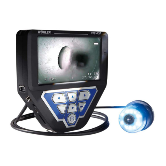
Page 10: Design And Function
Design and function Design and function Monitor 8, 9 Fig. 1: Monitor and components Legend Front and side view: Display Loudspeaker Control panel Card slot for memory card Mini USB port Power pack connection Video out Eyelet to secure shoulder strap Eyelet to secure wrist strap Microphone Test Equipment Depot - 800.517.8431 - 99 Washington Street Melrose, MA 02176... - Page 14 Design and function If the Additional Illumination, type plug-in, is in stalled (article 4194 ), the LEDs of the camera head and the pluggable illumination (article 4194) will be switched on and off at the same time. MENU key: Make settings PLAY key Playback recorded videos HOME key...
- Page 18 Connections Connecting the camera cable and camera head 5.2.1 Connecting the camera cable • Flip up the eight-pole female connector locat ed on the rear of the monitor (Fig 2, part 12). • Insert the male connector of the camera cable or rod into the female·...
- Page 22 Switching on the system and monitor • To switch on the device, briefly press the ON/OFF key at the bottom of the control pan • When the device is switched on, the light fram ing the ON/OFF key lights up green. The video image is displayed on the monitor after about 5 seconds.
- Page 26 Monitor settings ,,Option" - menu: Automatic • Press M to select the third icon (Option). shutdown • Press or - to select the time after which the monitor menu shall turn off automatically: 5 s > 10s>off. Note! � "OFF" is the default setting, so that the automatic shutdown will be desactivated.
-
Page 30: Calendar Menu
Making settings via the menu ON: Transmitter is switched on OFF: Transmitter is switched off NOTE! � The camera consumes less power when the transmitter is switched off. However, it is not pos sible to locate the camera head when the transmit ter is switched off. -
Page 33: Information Displayed On The Monitor
10.1 Displaying the position of the camera head The position can only be displayed if a 26 mm or 40 mm Wohler camera head is connected. Pointer symbol A pointer symbol displayed in the top left corner of the screen always indicates the direction of gravity, meaning, towards the bottom. -
Page 37: Capture Images
Capture images • To delete the video, press the SHIFT key and then the DELETE key The prompt "DELETING FILE" is displayed on the screen for approximately 2 seconds. Once the file has been deleted, the image currently being transmitted from the camera head is displayed on the screen. -
Page 41: Maintenance
Maintenance Maintenance 18.1 Replacing the dome of � NOTE! the camera head Wohlers 0 1 ½ • pan&tilt camera head is supplied protected by a plastic dome, which can be re placed if necessary. For example, if it becomes scratched, it is optional to fit this camera head with a glass dome for use in dry working environments. - Page 44 Test Equipment Depot - 800.517.8431 - 99 Washington Street Melrose, MA 02176 TestEquipmentDepot.com...
Need help?
Do you have a question about the VIS 400 and is the answer not in the manual?
Questions and answers