Wohler VIS 400 Operating Manual
Hide thumbs
Also See for VIS 400:
- Operating manual (39 pages) ,
- Operating manual (44 pages) ,
- Manual (50 pages)
Table of Contents
Advertisement
Quick Links
Advertisement
Table of Contents

Related Manuals for Wohler VIS 400


Summary of Contents for Wohler VIS 400
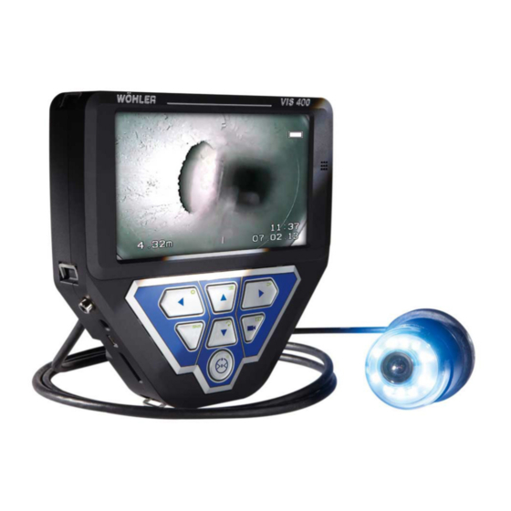
- Page 1 Operating manual Colour monitor Wöhler VIS 400 The measure of technology...
-
Page 2: Table Of Contents
Contents Contents General Information ......5 Operation Manual Information ....... 5 Notes ............. 5 Proper use ............. 5 Basic features ..........6 Transporting ..........6 Information on disposal ......... 6 Manufacturer ..........6 Important information ......7 Technical data ........9 Design and function ...... - Page 3 Contents Format ............24 9.3.1 Turning the screen view ....... 24 9.3.2 Changing the screen format ......24 9.3.3 Selecting the video standard ....... 24 Submenu „Option“ - Automatic shutdown ..24 Settings via the menu ......26 10.1.1 SETUP menu ..........27 10.1.2 CALENDAR menu ........
- Page 4 Contents 20.1 Warranty ............40 20.2 Service ............40 Accessories ......... 41 Declaration of conformity EG .... 42 Points of sale and service ......43...
-
Page 5: General Information
Wohler VIS 400 Colour Monitor. Please formation keep this manual for your information. The Wohler VIS 400 should be used by trained professionals for its intended use only. Warranty is voided by any damages caused by not following this manual. -
Page 6: Basic Features
0BGeneral Information Basic features Device Scope of supply Wöhler VIS 400 colour Colour monitor monitor 12 V rechargeable battery Power pack: 18 V, 1.5 SD memory card 4 GB Protective case with anti-glare visor and carry strap Transporting To prevent damage to the Monitor use the original carrying case when transporting. -
Page 7: Important Information
Important information Important information Eye protection WARNING! Never point a connected camera head at your own or somebody else's eyes when the monitor is switched on. The LEDs are extremely bright and can cause eye damage. WARNING! When connected, guide the rod with due care and attention. - Page 8 Important information Extraneous influences NOTE! Extraneous influences such as static discharges can cause the device to malfunction. If a malfunc- tion occurs, switch the monitor off and on again.
-
Page 9: Technical Data
Technical data Technical data Description Details TFT display 7"/ 16:9 format Recording Scope of delivery: 4 GB SD card (2.5 h recording capacity) Optional memory cards Max. 32 GB Technology: SD or SDHC Velocity class: 2 - 10 Formatting: For cards < 4 GB: FAT or FAT32, others: FAT 32 Interface Mini USB port Video output... -
Page 10: Design And Function
Design and function Design and function Monitor Fig. 1: Monitor and components Legend Front and side view: Display Loudspeaker Control panel Card slot for memory card Mini USB port Power pack connection Video out Eyelet to secure shoulder strap Eyelet to secure wrist strap 10 Microphone... - Page 11 Design and function Fig. 2: Monitor - rear view Legend Rear: 11 Battery compartment 12 Connection socket for camera cable or 13 Cable guide 14 Standard telescopic stand connection...
-
Page 12: Control Panel
Design and function Control panel Fig. 3: Control panel The keys on the control panel have the following functions: ON/OFF key turns the whole camera system on/off (monitor and connected camera head). NOTE! The ON/OFF key is framed by a green light when the monitor is switched on and the battery is charged. - Page 13 Design and function Camera head operating keys (this function is active only if the pan&tilt camera head is connected, see accessories) Tilt the camera head 180° Camera head operating keys (this function is active only if the pan&tilt camera head is connected, see accessories). Rotate the camera head 360°...
- Page 14 Design and function If the Additional Illumination, type plug-in, is in- stalled (article 4194), the LEDs of the camera head and the pluggable illumination (article 4194) will be switched on and off at the same time. MENU key: Make settings PLAY key Playback recorded videos HOME key...
-
Page 15: Connections
Connections Connection options The Wöhler VIS 400 monitor is a component of an expandable modular inspection sys- tem that the user can configure to meet the demands of any working environment. The various connection options are described below; please also refer to the Section Acces- sories. -
Page 16: Camera Heads
Connections 5.1.1 Camera heads The camera head selected affects the display options on the monitor. It is possible to connect the following camera heads: Diameter Ø 51 mm Ø 51 mm Ø 40 mm Ø 26 mm Image Colour ... -
Page 17: Camera Cable
Connections 5.1.2 Camera cable The most effective method of inspecting things such as chimney and downpipes is from above, for example when standing on the roof. To do so, it is necessary to connect a camera cable to the moni- tor. -
Page 18: Connecting The Camera Cable And Camera Head
Connections Connecting the camera cable and camera head 5.2.1 Connecting the camera cable Flip up the eight-pole female connector locat- • ed on the rear of the monitor (Fig 2, part 12). Insert the male connector of the camera cable •... -
Page 19: Connecting The Camera Head
Connections Allow the cable to hang down when you carry • the monitor with the shoulder strap over your shoulder. Fig. 10: Carrying the camera in the cam- era case 5.2.2 Connecting the camera head Insert the male cable connector (or male camera rod connector) at the other end into the eight-pole female connector of the camera head, then turn the locking ring clockwise to secure the connec-... -
Page 20: Rechargeable Battery Status And Recharging
Rechargeable battery status and recharging Rechargeable battery status and recharging WARNING! Risk of injury when handling the rechargeable batteries improperly! Never open the rechargeable battery housing. Do not throw rechargeable batteries into a fire or expose to high temperatures. There is a risk of explosion! If handled improperly, a liquid may emerge from rechargeable batteries that can cause skin irrita-... -
Page 21: Switching On The System And Monitor
Switching on the system and monitor Charging rechargeable batteries To recharge the battery, proceed as follows: • Connect the power pack to the charger con- nection of the device and the main power supply. The lower half of the light framing the ON/OFF key flashes red during the recharging process;... -
Page 22: Monitor Settings
Monitor settings Monitor settings On the left hand of the monitor there are 5 open- ings. With a pointed object press into these open- ings to adjust the monitor settings. Fig. 14: openings for adjusting the monitor settings Monitor Menu Select pa- reduce increase... -
Page 23: Setting The Picture Parameters In The Monitor Menu
Monitor settings Press to select the language • Setting the picture parameters in the monitor menu 8.2.2 In the picture menu, the brightness, the contrast and the color can be adjusted from 0 to 100 Note! The default settings are: Bright: 30 Contrast: 30 Color: 50... -
Page 24: Format
Monitor settings Format In the Format Menu the user can turn round the screen, the screen format can be changed from 16:9 to 4:3 and the video format can be selected. Press M to select the second icon (Format). • Fig. - Page 25 Monitor settings „Option“ - menu: Automatic Press M to select the third icon (Option). • shutdown – Press to select the time after which the • monitor menu shall turn off automatically: 5 s > 10 s > off. Note! “OFF”...
-
Page 26: Settings Via The Menu
Settings via the menu Settings via the menu After switching on the device, press the SHIFT • The green light framing the SHIFT key lights up and an S is displayed in the middle at the bottom of the monitor. This indicates that SHIFT mode is active and the second functions marked in green on the keys are enabled. -
Page 27: Setup Menu
Settings via the menu submenu line submenus settings Fig. 19: SETUP menu Navigating to the sumenu Using the up/down arrows, navigate to the • submenu line. Using the left/right arrow keys navigate to the submenu. Navigating to the parameters Using the up/down arrows, navigate to the •... - Page 28 Settings via the menu tings To define Video Setting 3, proceed as follows: In the menu view, use the up arrow key to • navigate to the submenu line and then use the right arrow key to select the VIDEO tab. Adjust the settings as described in section 10.1.3 Adjust the following settings as required: •...
-
Page 29: Calendar Menu
Settings via the menu ON: Transmitter is switched on OFF: Transmitter is switched off NOTE! The camera consumes less power when the transmitter is switched off. However, it is not pos- sible to locate the camera head when the transmit- ter is switched off. -
Page 30: Video Menu
Settings via the menu NOTE The date will be recorded together with the video. TIME Set the time. The time will be recorded together with the video. DATE FORMAT Set the date format to either Day.Month.Year or Month/Day/Year TIME FORMAT 12h/24h Set the time format to either 12 hour format or 24 hour format. -
Page 31: Viper Menu
Settings via the menu 9.1.4 VIPER menu The VIPER menu is only active, when a cable reel is connected to the camera. With the arrow keys go to CABLE and select • 20 m or 30 m according to the cable length Click on the disc icon to save the setting. -
Page 32: Information Displayed On The Monitor
Information displayed on the monitor ble reel or viper (if connected) Information displayed on the monitor 10.1 Displaying the position of the camera head The position can only be displayed if a Ø 26 mm or Ø 40 mm Wöhler camera head is connected. -
Page 33: Home Function
Home function Home function It is only possible to activate the home function when the Ø 40 mm Wöhler camera head is connected. The home function ensures the camera head is automatically aligned to a straight position, ensur- ing the camera "looks straight ahead". Moreover, when the user presses the HOME key, the camera head aligns itself so that the display is parallel with the ground above (this function is... -
Page 34: Audio And Video Functions
Audio and video functions Audio and video functions 12.1 Recording Record video To begin recording a video, press the Record • video key. The RECORD VIDEO key is framed by a red flashing light when recording is in process, and a red dot is displayed on the screen. -
Page 35: Delete Files
Audio and video functions on the screen. NOTE! It is possible to distinguish a photo from the initial image of a video by the recording time which is displayed in the initial image of a video. Select the desired video using the right/left arrow keys. -
Page 36: Capture Images
Capture images audio file, if necessary), press the SHIFT key and then the PLAY key. The first image of the last video recorded is dis- played on the monitor. Select the video to be deleted using the • right/left arrow keys. To delete the video, press the SHIFT key and •... -
Page 37: Delete Files
Delete files Delete files To select the file to be deleted (including the • audio file, if necessary), press the SHIFT key and then the PLAY key. The first image of the last video recorded or the last image recorded is displayed on the monitor. Note! The recording time in the initial image of a video shows that it is a video and not a photo. -
Page 38: Guide Accessories
Guide accessories Guide accessories This section contains some recommendations based on our experience about the se- lection of guide accessories for the inspection in tubes and ducts. As all pipes and chimney systems are different, the user has to decide about the guide accessory in every single case. -
Page 39: Faults
Faults Faults Fault description Possible cause To rectify Cannot start monitor. Rechargeable battery has Recharge battery or con- When the ON/OFF key is no charge left. nect monitor to electrical pressed, the light framing power supply the key briefly lights up red. -
Page 40: Maintenance
Clean the monitor using a soft cloth. Warranty and service 19.1 Warranty Each Wöhler VIS 400 Colour Monitor will be test- ed in all functions and will leave our factory only after extensive quality control testing. If used properly, the warranty period for the VIS 400 Colour Monitor will be 12 month from the date of sale. -
Page 41: Accessories
Wöhler Camera Head Colour Ø 40 mm, pan and tilt Order no. 8930 Wöhler Miniature Camera Head Colour Ø 26 mm Order no. 8920 Wöhler Cable Reel Wöhler VIS 400 Order no. 7816 Wöhler Camera Viper 42 with GRP camera rod Order no. 7307 Wöhler VIS Guidance Set 100... -
Page 42: Declaration Of Conformity Eg
Declaration of conformity EG Declaration of conformity EG WÖHLER Technik GmbH Wöhler-Platz 1, D-33181 Bad Wünnenberg Declares that the following product: Complies with the safety requirements set out in the directives of the European parlia- ment and council on the approximation of laws of the Member States relating to electro- magnetic compatibility (2014/30/EU) and low voltage (2014/35/EU). -
Page 43: Points Of Sale And Service
Gneisenaustr.12 80992 Munich Tel.: +49 89 1589223-0 Fax: +49 89 1589223-99 sued@woehler.de International Czech Republic Wohler USA Inc. Wöhler Bohemia s.r.o. 5 Hutchinson Drive Za Naspern 1993 Danvers, MA 01923 393 01 Pelhrimov Tel.: +1 978 750 9876 Tel.: +420 565 349 011 Fax.: +1 978 750 9799...
Need help?
Do you have a question about the VIS 400 and is the answer not in the manual?
Questions and answers