Table of Contents
Advertisement
Change for life
Owner's Manual
Original Instructions
Local air conditioner
Model: GPC07AM-K5NNA2B
GPC07AM-K5NNA2C
GPC09AM-K5NNA2B
Thank you for choosing our product.
Please read this Owner's Manual carefully before operation and
retain it for future reference.
If you have lost the Owner's Manual, please contact the local agent
or visit www.gree.com or send an email to global@gree.com.cn for
the electronic version.
Advertisement
Table of Contents

Related Manuals for Gree GPC07AM-K5NNA2B


Summary of Contents for Gree GPC07AM-K5NNA2B
- Page 1 Thank you for choosing our product. Please read this Owner’s Manual carefully before operation and retain it for future reference. If you have lost the Owner's Manual, please contact the local agent or visit www.gree.com or send an email to global@gree.com.cn for the electronic version.
-
Page 2: Table Of Contents
Content Operation Notices The Refrigerant ......................1 Safety Warning ......................2 Operation Environment ....................3 Part's Name ......................4 Operation Guide Operation Introduction for Control Panel ..............5 Buttons on Remote Controller .................7 Introduction for icons on display screen ..............7 Introduction for Buttons on Remote Controller ............8 Function Introduction for Combination Buttons ............10 Replacement of Batteries in Remote Controller .............1 0 Maintenance... - Page 3 Explanation of Symbols Indicates a hazardous situation that, if not avoided, will DANGER result in death or serious injury. Indicates a hazardous situation that, if not avoided, could WARNING result in death or serious injury. Indicates a hazardous situation that, if not avoided, may CAUTION result in minor or moderate injury.
-
Page 4: The Refrigerant
Appliance filled with flammable gas R290. Applia nce shall be installed, operated and stored in a room with a floor area: Model Min. floor area (m ) GPC07AM-K5NNA2B GPC07AM-K5NNA2C GPC09AM-K5NNA2B The appliance shall be stored in a room without continuously operating ignition sources . -
Page 5: Safety Warning
Safety Warning ● This appliance can be used by children aged from 8 years and above and persons with reduced physical, sensory or mental capabilities or lack of experience and knowledge if they have been given supervision or instruction concerning use of the appliance in a safe way and understand the hazards involved. -
Page 6: Operation Environment
Safety Warning ● Do not use an extension cord. ● Do not through sundries into the air duct. If there are sundries get into the air duct, please contact the professionals to deal with it. Operation Environment ● The air conditioner must be operated within the temperature range: 16°C ~ 35°C. -
Page 7: Part's Name
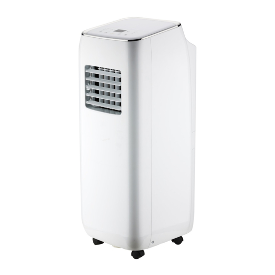
Part's Name Controller panel Guide louver Swing louver Castor Filter Joint Heat discharge pipe Window adapter Plug of power cord Wire-fixing hook Remote controller NOTICE: Heat discharge pipe and other installation accessories can't be discarded. -
Page 8: Operation Introduction For Control Panel
Operation Introduction for Control Panel Name of control panel Dual-8 nixie tube Cool mode indicator + / - button Dry mode indicator Fan speed indicator Fan mode indicator Wifi button Sleep button Mode button ON/OFF button Fan button Operation of control panel Note: ●... - Page 9 Operation Introduction for Control Panel Mode button Press this button and the mode will circulate according to below sequence: → COOL COOL: Under this mode, cooling mode indicator is bright. Dual-8 nix set temperature. Temperature setting range is 16°C~30°C. DRY: Under this mode, drying mode indicator is bright. Dual-8 nixie tube won’t display.
-
Page 10: Buttons On Remote Controller
Buttons on remote controller On/Off button Mode button + / - button Swing button Fan button Sleep button Timer button Health button WiFi button Introduction for icons on display screen Temp. display type :Set temp. :Indoor ambient temp. :Outdoor ambient temp. Turbo mode Set fan speed Send signal... -
Page 11: Introduction For Buttons On Remote Controller
Introduction for buttons on remote controller Note: ● This is a general use remote controller, it could be used for the air conditioners with multifunction; For some function, which the model doesn't have, if press the corresponding button on the remote controller that the unit will keep the original running status. - Page 12 Introduction for buttons on remote controller Swing button Press this button to turn “ON” & “OFF” swing. Fan button This button is used for setting Fan Speed in the sequence that goes from AUTO, , to then back to Auto. Auto Speed 1 Speed 2...
-
Page 13: Function Introduction For Combination Buttons
Introduction for buttons on remote controller WiFi button Press " WiFi " button to turn on or turn off WiFi function. When WiFi function is turned on, the " WiFi " icon will be displayed on remote controller; Under status of unit off, press "Mode"... -
Page 14: Clean And Maintenance
Clean and Maintenance WARNING ● Before cleaning the air conditioner, please turn off the unit and disconnect power. Otherwise, it may cause electric shock. ● Do not wash air conditioner with water. Otherwise, it may cause electric shock. ● Do not use volatile liquid (such as thinner or gas) to clean the air conditioner. Otherwise, it may damage the appearance of air conditioner. - Page 15 Clean and Maintenance Clean heat discharge pipe Remove the heat discharge pipe from air conditioner, clean and dry it , and then reinstall it. (For the method of installation and removal , please refer to the instruction for "Installation and disassembly of heat discharge pipe"). Checking before use-season 1.
-
Page 16: Malfunction Analysis
Malfunction Analysis Please check below items before asking for maintenance. If the malfunction still can’t be eliminated, please contact local dealer or qualified professionals. Phenomenon Troubleshooting Solution ● Power failure? ● Wait after power recovery. ● Is plug loose? ● Reinsert the plug. ●... - Page 17 Malfunction Analysis Phenomenon Troubleshooting Solution ● Whether air outlet or air inlet is ● Eliminate the obstacles. blocked? ● Under heating mode, whether ● The unit will stop blowing indoor temperature is reached fan after reaching set to set temperature? temperature.
- Page 18 Malfunction analysis Malfunction code ERROR Troubleshooting CODE Please contact qualified professionals for service. Please contact qualified professionals for service. Please contact qualified professionals for service. Please contact qualified professionals for service. 1.Check if the unit is under high-temperature and high-humidity environment; if ambient temperature is too high, power off the unit and then energize it for operation after the ambient temperature drops to 35 below.
-
Page 19: Installation Precaution
Installation Precaution WARNING ● Observe all governing codes and ordinances. ● Do not use damaged or non-standard power cord. ● Be caution during installation and maintenance. Prohibit incorrect operation to prevent electric shock, casualty and other accidents. Selection of installation location Basic requirement Installing the unit in the following places may cause malfunction. - Page 20 Installation Precaution Requirements for electric connection WARNING: Safety precaution 1. Must follow the electric safety regulations when installing the unit. 2. According to the local safety regulations, use qualified power supply circuit. 3. For appliances with type Y attachment,the instructions shall contain the substance of the following.If the supply cord is damaged,it must be replaced by the manufacturer, its service agent or similarly qualified persons in order to avoid a hazard.
-
Page 21: Preparation Before Installation
Preparation before Installation Note: check if the accessories are available before installation. Accessory list Window Window Joint Adapter heat discharge pipe adapter(top) adapter(bottom) battery (AAA 1.5V) wire hook screw remote controller user's manual Optional Note: some models are without the following accessories. Window panel Exhaust cover Adjustment panel... -
Page 22: Install Wire Hook
Install Wire Hook ● Assemble the wire hook at the back of the unit with screws (the direction of wire direction of wire hook is upward wire hook screw direction of wire hook is downward ● Wind the power cord around the wire hook. -
Page 23: Removing Collected Water
Removing Collected Water There are 2 ways to remove collected water: Use the continuous drainage option from the bottom hole ■ Drainage way as follows. 1. In Cool or Dry mode operating, the condensation water will be drained to the chassis. 2. - Page 24 Removing Collected Water Use the continuous drainage option from the middle hole Note: Water can be automatically emptied into a floor drain by attaching 14mm inner diameter hose (not included). Remove the continuous drain cap 1 by turning it counter clockwise then remove the rubber stopper 2 from the spout.
-
Page 25: Installation In A Double-Hung Sash Window(Optional)
Installation in a double-hung sash window(Optional) 1. Connect the rain guards to the insect guard net. Insert all three projections on each rain guard into the holes in the insect guard net. Side “A” will now be at the top, as indicated in the diagram. Hole Insect guard net Rain guard... - Page 26 Installation in a double-hung sash window(Optional) The window panel cannot be installed in windows less than 20.5" (520mm) wide, as you will be unable to shut the exhaust cover. (1) Open the window sash and place the window panel on the window sill. (2) Secure the window panel to the window stool with screws.
- Page 27 Installation in a double-hung sash window(Optional) 5. Close the window sash securely against the Window panel. 6. Stuff the Foam seal A between the glass and the window to prevent air and insects from getting into the room. 7. Attach the bracket with a screw.(Recommended) Bracket Please lay a tabular material underneath the window panel in case you could not attach the rain guard or the window adapter properly due to the deep...
-
Page 28: Installation In A Sliding Sash Window(Optional)
Installation in a sliding sash window(Optional) 1. Connect the rain guards to the insect guard net. Insert all three projections on each rain guard into the holes in the insect guard net. Side “A” will now be at the top, as indicated in the diagram. "A"... - Page 29 Installation in a sliding sash window(Optional) The window panel cannot be installed in windows less than 20.5" (520mm) high, as you will be unable to shut the exhaust cover. (1) Open the window sash and place the window panel on the window frame. (2) Secure the window panel to the window frame with screws.
- Page 30 Installation in a sliding sash window(Optional) 4. Close the window sash securely against the Window panel. 5. Stuff the Foam seal A between the glass and the window to prevent air and insects from getting into the room. 6. Attach the bracket with a screw.(Recommended) Bracket Please lay a tabular material underneath the window panel in case you could not attach the rain guard or the window adapter properly due to the deep...
-
Page 31: Installation And Disassembly Of Heat Discharge Pipe
Installation and Disassembly of Heat Discharge Pipe Install heat discharge pipe 1. Install window adapter— aim the window adapter(top) at the window adapter(bottom),fix them together,press the clasp forcibly in to the groove. Window adapter(top) Window adapter(bottom) 2. Rotate joint and window adapter clockwise into the two ends of heat discharge pipe. clockwise clockwise joint... - Page 32 Installation and Disassembly of Heat Discharge Pipe Note of Installing heat discharge pipe The discharge pipe is suggested to be installed according to below figure by the manufacturer. under 51 inchs correct about 24 inchs User can adjust the installation method of the discharge pipe basing on the requirement, while the similar installation methods as below which will lead to unsmoothly air-out are not allowed.
- Page 33 Installation and Disassembly of Heat Discharge Pipe Disassemble heat discharge pipe 1. Remove joint: Press the clasp and lift joint upwards to remove it. clasp upwards disassemble joint 2.Remove window adapter from outdoors. window adapter 3.Remove the window adapter. Pull out and remove the window adapter by pushing down two “PUSH”...
-
Page 34: Operation Test
Operation Test ● Put through the power supply and then press ON/OFF button on remote contro- ller to start the unit. ● Press mode button to select auto, cooling, drying, fan or heating function, and then check if the unit operates normally. ●... -
Page 35: Specialist's Manual
Specialist’s Manual Aptitude requirement for maintenance man(repairs should be done only be specialists). a. All the work men who are engaging in the refrigeration system should bear the valid certification awarded by the authoritative organization and the qualification for dealing with the refrigeration system recognized by this industry. b. - Page 36 Specialist’s Manual Refrigeration equipment Checking Where electrical components are being changed, they shall be fit for the purpose and to the correct specification. At all times the manufacturer’s maintenance and service guidelines shall be followed. If in doubt, consult the manufacturer’s technical department for assistance.
- Page 37 Specialist’s Manual Ensure that the apparatus is mounted securely. Ensure that seals or sealing materials have not degraded to the point that they no longer serve the purpose of preventing the ingress of flammable atmospheres. Replacement parts shall be in accordance with the manufacturer’s specifications. NOTE : The use of silicon sealant can inhibit the effectiveness of some types of leak detection equipment.
- Page 38 Specialist’s Manual The refrigerant charge shall be recovered into the correct recovery cylinders. For appliances containing flammable refrigerants, the system shall be “flushed” with OFN to render the unit safe. This process may need to be repeated several times. Compressed air or oxygen shall not be used for purging refrigerant systems. For appliances containing flammable refrigerants, flushing shall be achieved by breaking the vacuum in the system with OFN and continuing to fill until the working pressure is achieved, then venting to atmosphere, and finally pulling down to a vacuum.
- Page 39 Specialist’s Manual f) Make sure that cylinder is situated on the scales before recovery takes place. g) Start the recovery machine and operate in accordance with manufacturer's instructions. h) Do not overfill cylinders. (No more than 80 % volume liquid charge). i) Do not exceed the maximum working pressure of the cylinder, even temporarily.
- Page 40 GREE ELECTRIC APPLIANCES, INC. OF ZHUHAI Add: West Jinji Rd, Qianshan, Zhuhai,Guangdong, China, 519070 Tel: (+86-756) 8522218 Fax: (+86-756) 8669426 E-mail: gree@gree.com.cn Web: www.gree.com 600005061860...
Need help?
Do you have a question about the GPC07AM-K5NNA2B and is the answer not in the manual?
Questions and answers