Table of Contents
Advertisement
Available languages
Available languages
Instrukcja obsługi ZSP135-DR
MERAWEX Sp. z o.o.
44-122 Gliwice
ul. Toruńska 8
tel. +48 32 23 99 400
fax +48 32 23 99 409
e-mail:
merawex@merawex.com.pl
http://www.merawex.com.pl
Zasilacz do urządzeń sygnalizacji pożarowej, systemów kontroli rozprzestrzeniania
dymu i ciepła oraz urządzeń przeciwpożarowych i automatyki pożarowej
ZSP135-DR-2A-1, ZSP135-DR-3A-1, ZSP135-DR-3A-2,
ZSP135-DR-5A-1, ZSP135-DR-5A-2, ZSP135-DR-5A-3,
ZSP135-DR-7A-1, ZSP135-DR-7A-2, ZSP135-DR-7A-3
zgodnych z normami EN 54-4:1997 + AC:1999 + A1:2002 + A2:2006
wytycznymi VdS 2541:1996-12, 2882:2004-11, 2824:2004-03, 2593:2002-09
oraz Rozp. MSWiA z dnia 20.06.2007 Dz. U. Nr 143 Poz.1002
Certyfikat zgodności EC CNBOP-PIB Nr 1438/CPD/0163
Deklaracja właściwości użytkowych Nr DWU-MX-03
Świadectwo dopuszczenia CNBOP-PIB Nr 3647/2019
1.
2.
3.
4.
5.
6.
7.
0404.00.95-05.4
INSTRUKCJA OBSŁUGI
i EN 12101-10:2005 + AC:2007,
(ze zmianami z dn. 27.04.2010)
w obudowie o stopniu ochrony IP44
18.10.2019 r.
Świadectwo dopuszczenia VdS Nr G 511007
1/36
2
4
7
7
10
11
12
Advertisement
Chapters
Table of Contents

Related Manuals for MERAWEX ZSP135-DR-2A-1


Summary of Contents for MERAWEX ZSP135-DR-2A-1
-
Page 1: Table Of Contents
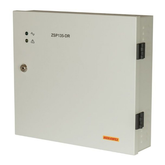
Instrukcja obsługi ZSP135-DR 0404.00.95-05.4 1/36 MERAWEX Sp. z o.o. 44-122 Gliwice ul. Toruńska 8 tel. +48 32 23 99 400 fax +48 32 23 99 409 e-mail: merawex@merawex.com.pl http://www.merawex.com.pl INSTRUKCJA OBSŁUGI Zasilacz do urządzeń sygnalizacji pożarowej, systemów kontroli rozprzestrzeniania dymu i ciepła oraz urządzeń przeciwpożarowych i automatyki pożarowej... -
Page 2: Opis Techniczny
Instrukcja obsługi ZSP135-DR 0404.00.95-05.4 2/36 Ostrzeżenia Należy przeczytać wszystkie poniższe wskazówki i przepisy. Błędy w ich przestrzeganiu mogą spowodować uszkodzenie urządzenia, porażenie prądem, pożar lub ciężkie obrażenia ciała. ▪ Zabrania się przenoszenia i transportu urządzenia z zamontowanymi i dołączonymi akumulatorami. Może to spowodować powstanie poważnych wewnętrznych uszkodzeń do utraty bezpieczeństwa użytkowania włącznie. - Page 3 Parametry prądowe zasilaczy Imax_a EN 12101-10 Pojemność Imax_a Typ zasilacza Imax_b szafki baterii EN 54-4 72 h 30 h ZSP135-DR-2A-1 18 Ah 1.0 A 0.16 A 0.42 A 1.00 A ZSP135-DR-3A-1 18 Ah 2.0 A 0.16 A 0.42 A 2.00 A...
-
Page 4: Instalowanie I Podłączenie
Instrukcja obsługi ZSP135-DR 0404.00.95-05.4 4/36 ZSP135-DR M E RAWEX Rys. 1. Widok, wymiary gabarytowe i rozmieszczenie otworów mocujących dla przykładowego zasilacza ZSP135-DR-5A-1. 2. Instalowanie i podłączenie ▪ Podczas montażu i instalacji urządzenia należy stosować się do niniejszej Instrukcji Obsługi. - Page 5 Instrukcja obsługi ZSP135-DR 0404.00.95-05.4 5/36 Podejście z przewodami instalacyjnymi możliwe jest od góry poprzez umieszczone tam trzy dławnice DW20-RM i jedną DW16-RM (dedykowaną kablom sygnalizacji zdalnej). Wszystkie połączenia należy wykonać zgodnie z rysunkiem umieszczonym wewnątrz urządzenia na drzwiach szafki. Otwory niewykorzystanych dławnic należy zaślepić...
- Page 6 Instrukcja obsługi ZSP135-DR 0404.00.95-05.4 6/36 akumulatory należy ustawić na dnie szafki. Montaż akumulatorów należy rozpocząć od ich podłączenia do pakietu głównego zasilacza, a następnie połączyć je między sobą. Należy zwrócić szczególną uwagę na biegunowość podłączenia akumulatorów. Przy błędnym podłączeniu nastąpi uszkodzenie bezpiecznika obwodu akumulatora.
-
Page 7: Pierwsze Uruchomienie
Instrukcja obsługi ZSP135-DR 0404.00.95-05.4 7/36 IN PU T P 336.4 Q1 01 K1 01 FUSE 3. Pierwsze uruchomienie Jeżeli wszystkie połączenia zostały wykonane poprawnie po załączeniu zasilacza do sieci elektroenergetycznej powinny zapalić się diody sygnalizacyjne (diody 8 i 9 MAINS OPERATION wewnątrz szafki na pakiecie zasilacza –... - Page 8 Instrukcja obsługi ZSP135-DR 0404.00.95-05.4 8/36 zauważone. Dla napięć pośrednich uruchamiana jest sygnalizacja ostrzegawcza w postaci krótkich błysków diody FAULT, lecz sama bateria nie zostanie dołączona. W trybie pracy bateryjnej, przy braku zasilania sieciowego, po rozładowaniu baterii, jest ona odłączana przez przekaźnik (RGR), dlatego nie ma zagrożenia zniszczenia akumulatorów przez ich całkowite rozładowanie.
- Page 9 Instrukcja obsługi ZSP135-DR 0404.00.95-05.4 9/36 Praca bateryjna Uszkodzenie baterii przy obecności sieci Uszkodzenie baterii przy braku sieci Przekaźnik MAINS FLT reaguje na zanik zasilania sieciowego z 5-sekundową zwłoką. Uwaga Zamieszczony w tabelach powyżej i poniżej rysunek styków przekaźnika odpowiada rysunkowi umieszczonemu na pakiecie zasilacza obok zacisków przyłączeniowych danego przekaźnika.
-
Page 10: Serwis
Instrukcja obsługi ZSP135-DR 0404.00.95-05.4 10/36 uruchomienie, a ponadto sprawdzić czy sygnał uszkodzenia wygenerowany w zasilaczu jest transmitowany do Centrali Sygnalizacji Pożarowej. 5. Serwis 5.1. Bezpieczniki Użytkownik może dokonać wymiany tylko wskazanych poniżej bezpieczników. ZSP135-DR-5A Oznaczenie ZSP135-DR-2A na rysunku ZSP135-DR-7A ZSP135-DR-3A Obwód akumulatora (szybki F) 5 AF 10 AF... -
Page 11: Uwagi Na Temat Wyboru Typu Zasilacza
Instrukcja obsługi ZSP135-DR 0404.00.95-05.4 11/36 − bezpieczniki wyjściowe (4,5) Brak napięcia na jednym − kontakty elektryczne na z wyjść odpowiednim złączu wyjściowym − bezpiecznik baterii (3) − podłączenie akumulatorów Brak podtrzymania napięcia (bateria nie podłączona lub na obu wyjściach podczas niewłaściwie podłączona) zaniku zasilania sieciowego −... -
Page 12: Informacje Dodatkowe
Instrukcja obsługi ZSP135-DR 0404.00.95-05.4 12/36 - prąd pobierany przez odbiory w czasie trwania alarmu [A] - czas trwania alarmu [h] (0.5 h) - prąd pobierany przez urządzenia wykonawcze w czasie trwania alarmu [A] - czas trzech pełnych cykli pracy urządzeń wykonawczych [h] Uwaga: zasilacz wymaga pewnej minimalnej pojemności baterii w czasie dozorowania i alarmu na pokrycie swoich potrzeb własnych (Iz = 0.035 A). - Page 13 User manual ZSP135-DR 0404.00.95-05.4 13/36 MERAWEX Sp. z o.o. 44-122 Gliwice Toruńska 8, Poland tel. +48 32 23 99 400 fax +48 32 23 99 409 e-mail: merawex@merawex.com.pl http://www.merawex.com.pl USER MANUAL Power supply for fire detection and fire alarm systems, smoke and heat control...
-
Page 14: Technical Description
User manual ZSP135-DR 0404.00.95-05.4 14/36 Warnings Please read all these tips and regulations. Mistakes in their observance may cause damage, electric shock, fire or serious injury. ▪ It is forbidden to carry and transport the device with mounted and connected batteries. This can cause severe internal faults and can lead to the loss of operation safety. - Page 15 Type of Imax_a EN 12101-10 Imax_a Battery Type Imax_b the box capacity EN 54-4 72 h 30 h ZSP135-DR-2A-1 18 Ah 1.0 A 0.16 A 0.42 A 1.00 A ZSP135-DR-3A-1 18 Ah 2.0 A 0.16 A 0.42 A 2.00 A...
-
Page 16: Set-Up
User manual ZSP135-DR 0404.00.95-05.4 16/36 ZSP135-DR M E RAWEX Figure 1. View, dimensions and mounting holes layout for the exemplary power supply ZSP135- DR-5A 2. Set-up ▪ During set-up apply directions of this manual ▪ Mount devices in a place without direct insolation ▪... - Page 17 User manual ZSP135-DR 0404.00.95-05.4 17/36 PR AC A ZASI LAN I E B302 B A T E R I A WY J 1 WY J 2 A LA R M ZB Z A N I K Z AS A L Z E W S I E C ~230V Figure 2 View of the power supply ZSP135-DR.
- Page 18 User manual ZSP135-DR 0404.00.95-05.4 18/36 with other. One has to pay due attention to the right polarity of the connection. In case of erroneous connection of the battery circuit a fuse shall blow. Remark: Following the recommendations of the VdS for installations requiring the use of devices with VdS Approval, only VdS Approved batteries can be installed.
-
Page 19: First Start
User manual ZSP135-DR 0404.00.95-05.4 19/36 IN PU T P 336.4 Q1 01 K1 01 FUSE 3. First start If all connections have been carried out correctly, then after having the power supply connected to the mains the indication LEDs (diodes 8 and 9 inside the cabinet on the circuit pack MAINS OPERATION –... - Page 20 User manual ZSP135-DR 0404.00.95-05.4 20/36 Note 1 Disconnecting the battery from the load after its discharging prevents the battery from damage, but only under a condition that the mains power failure will not last too long (e.g. several days). No battery recharging, for long time, can cause spontaneous decrease of its voltage, preventing its automatic connection when the mains is back.
- Page 21 User manual ZSP135-DR 0404.00.95-05.4 21/36 yellow LED relay Fault FAULT BAT FLT Mains power failure – including a failure of the converter Battery bank not present or voltage of the connected bank below 10 V Low voltage (<24 V) during battery test High resistance (>250 mΩ)of the battery circuit Blown battery fuse Battery discharged (<22 V) during battery mode...
-
Page 22: Repairs
User manual ZSP135-DR 0404.00.95-05.4 22/36 5. Repairs 5.1. Fuses A user can replace only the fuses shown below. ZSP135-DR-5A Markings on ZSP135-DR-2A the Fig. 4 ZSP135-DR-7A ZSP135-DR-3A Battery circuit (quick-break F) 5 AF 10 AF 4, 5 Output circuit (quick-break F) 5 AF 10 AF 1, 2... -
Page 23: Remarks On The Selection Of The Type Of The Power Supply
User manual ZSP135-DR 0404.00.95-05.4 23/36 − battery fuse (3) No backup − connection of the batteries (the battery not voltage on both outputs in case of connected or connected incorrectly) − state of the batteries a mains power failure − The device quality of the connections of the batteries −... -
Page 24: Additional Information
User manual ZSP135-DR 0404.00.95-05.4 24/36 - duration of three full work cycles of the actuator [h] Attention: the power supply requires some minimal battery capacity during the standby and alarm for its own needs (I = 0.035 A). This is 3.3 Ah for the standby of 72 h, 1.4 Ah for 30 h, and 0.20 Ah for 4 h. Having calculated from the above formula the required capacity of the battery bank, one can use the table in the section 1.1 to select the power supply, observing the constraint of the maximal capacity to mount in the given power supply and choosing the standard value which must be greater than the... - Page 25 Handbuch ZSP135-DR 0404.00.95-05.4 25/36 MERAWEX Sp. z o.o. Toruńska 8 44-122 Gliwice, Polen Tel. +48 32 23 99 400 Fax +48 32 23 99 409 E-Mail: merawex@merawex.com.pl http://www.merawex.com.pl HANDBUCH Netzteile für Brandmeldeanlagen, Rauch- und Wärmeabzugsanlagen und andere Brandschutzsysteme ZSP135-DR-2A-1, ZSP135-DR-3A-1, ZSP135-DR-3A-2,...
- Page 26 Handbuch ZSP135-DR 0404.00.95-05.4 26/36 Warnhinweise: Lesen Sie unbedingt alle Hinweise durch. Nichtbeachtung dieser Anweisung könnte die Beschädigung des Gerätes, Brand oder schwere Körperverletzung verursachen. ▪ Es ist verboten das Gerät mit eingebauten und angeschlossenen Akkus zu bewegen oder befördern. Es kann zu ernsten inneren Beschädigungen führen, einschließlich bis den Verlust des sicheren Verbrauch.
- Page 27 Temperatur über 40°C an dem Installationsort vermieden werden. Stromparameter der Netzteilen Imax_a EN 12101-10 Imax_a Batterie- Gehäusetyp Imax_b kapazität EN 54-4 72 h 30 h ZSP135-DR-2A-1 18 Ah 1.0 A 0.16 A 0.42 A 1.00 A ZSP135-DR-3A-1 18 Ah 2.0 A 0.16 A 0.42 A 2.00 A...
- Page 28 Handbuch ZSP135-DR 0404.00.95-05.4 28/36 ZSP135-DR M E RAWEX Abb. 1 Außenansicht und Ausmaßen des exemplarischen Netzteils (ZSP135-DR-5A-1) und Position der Montagelöcher 2. Inbetriebnahme ▪ Befolgen Sie bei der Einrichtung die Anweisungen in diesem Handbuch ▪ Montieren Sie das Gerät an einem Ort ohne direkt Sonneneinstrahlung ▪...
- Page 29 Handbuch ZSP135-DR 0404.00.95-05.4 29/36 Tür) ausgeführt werden. Wird eine Stopfbüchse nicht verwendet, soll das dafür vorgesehene Loch mit der mitgelieferten Kappe verschlossen werden. PR AC A ZASI LAN I E B302 B A T E R I A WY J 1 WY J 2 A LA R M ZB Z A N I K Z AS...
- Page 30 Handbuch ZSP135-DR 0404.00.95-05.4 30/36 Konfiguration des Summensignals für die Störung 2.3. In Anlehnung an die Relaisausgänge der Störungen kann der MAINS FLT BATTERY FLT Summenausgang für das Störungssignal konfiguriert werden. Er signalisiert auf einer Linie das Auftreten jedes durch die beiden Signale erfassten Ereignisses. Je nach Belegung der Relaiskontakte (Schließer oder Öffner im potentialfreien Zustand), ist eine entsprechende Verbindung der beiden Relais auszuführen.
- Page 31 Handbuch ZSP135-DR 0404.00.95-05.4 31/36 Prüfung der unterbrechungsfreien Verfügbarkeit der Ausgangsspannung 3.1. Betätigen Sie einen Leistungsschalter der Netzversorgung, um das Netzteil ZSP135-DR vom Stromnetz zu trennen. Das Netzteil soll nun in den Batteriebetrieb wechseln und dabei die Spannung an beiden Ausgängen halten. Dies kann mit einem beliebigen Messgerät überprüft werden, z.B. mit einem Voltmeter oder einer Glühbirne.
- Page 32 Handbuch ZSP135-DR 0404.00.95-05.4 32/36 Einrichtung zur Anzeige des Öffnens der Tür (optional) – die Klemmen auf 4.3. Anschlussstücke INT FLT Die Netzteile ZSP135-DR können optional mit einem Türöffnerkontakt ausgestattet werden. Das Öffnen der Tür (nach dem Aufschließen) führt zum Öffnen des Kontakts und löst eine Störung aus, die an der Tür des Gehäuses und die Änderung des Relaiszustands durch die blinkende LED FAULT...
- Page 33 Handbuch ZSP135-DR 0404.00.95-05.4 33/36 Anzeige über den Zustand des Netzbetriebs (LEDs auf der Platine) grüne LED gelbe LED Zustand des Netzbetriebs MAINS OPERATION Ordnungsgemäßer Netzbetrieb Wandler beschädigt Netzstromausfall Anzeige über den Zustand der Batterieanlage (LED auf der Platine) rote LED Zustand der Batterieanlage (BATTERIE) Batterie OK...
- Page 34 Handbuch ZSP135-DR 0404.00.95-05.4 34/36 Darüber hinaus befindet sich eine Schmelzsicherung B201 auf der Platine. Eine Beschädigung dieser Sicherung zeigt einen schwerwiegenden Fehler des Geräts an. Sie darf nicht vom Benutzer ausgetauscht werden. Garantiearbeiten und Reparaturen nach Ablauf der Garantie werden entweder vom Hersteller oder von einer berechtigten Partnerfirma durchgeführt.
- Page 35 Handbuch ZSP135-DR 0404.00.95-05.4 35/36 6. Anmerkungen zur Auswahl des Netzteiltyps Die Netzteile ZSP135-DR haben verschiedene Ausgangsströme und arbeiten mit internen Batterien verschiedener Kapazitäten. Die Auswahl des entsprechenden Typs hängt von den Anforderungen der jeweiligen Auslastung ab. Zunächst muss die erforderliche Batteriekapazität berechnet werden. Dazu sind der Stromverbrauch während verschiedener Betriebszustände des versorgten Geräts sowie der zusätzliche Verbrauch für den Eigenbedarf während des Stromausfalls zu berücksichtigen.
- Page 36 Auswirkungen auf die menschliche Gesundheit und die Umwelt zu vermeiden. 1438 MERAWEX Sp. z o.o. - Toruńska 8, 44-122 Gliwice, Poland 1438/CPD/0163 EN 54-4:1997 + AC:1999 + A1:2002 + A2:2006, EN 12101-10:2005 + AC:2007 Zasilacz do urządzeń sygnalizacji pożarowej, systemów kontroli rozprzestrzeniania dymu i ciepła oraz urządzeń...
Need help?
Do you have a question about the ZSP135-DR-2A-1 and is the answer not in the manual?
Questions and answers