Advertisement
ZDSO400-DR2, ZDSO400-DR4
MERAWEX
MERAWEX
MERAWEX Sp. z o.o.
44-122 Gliwice
ul. Toruńska 8
POLAND
Phone: +48 32 23 99 400
Fax +48 32 23 99 409
e-mail:
merawex@merawex.com.pl
http://www.merawex.com.pl
standards: EN-54-4:1997+A1:2002+A2:2:2006 & EN-121001-10:2005,
1.
TECHNICAL DESCRIPTION .............................................................................. 2
2.
OPERATION PRINCIPLE ................................................................................... 6
3.
INSTALLATION AND CONNECTION ............................................................... 10
4.
FIRST START ................................................................................................... 11
5.
OPERATION ..................................................................................................... 14
6.
SERVICING ....................................................................................................... 16
7.
ADDITIONAL INFORMATION .......................................................................... 17
Prepared by:
Checked by:
Verified by:
Approved by:
Documentation N
Document N
USER MANUAL
Power supply units for sound alarm systems
ZDSO400-DR2, ZDSO400-DR4
certificate of constancy of performance 1438-CPR-0319
Mr. Adam Kretek
Mr. Zdzisław Klimasara
Mr. Dariusz Cygankiewicz
Mr. Grzegorz Szandar
o
: 0546.00.95-02.2
o
. 0546.00.95-02.2
type
complying with:
04.08-2015
Page:1/18
Advertisement

Related Manuals for MERAWEX ZDSO400-DR2


Summary of Contents for MERAWEX ZDSO400-DR2
-
Page 1: Table Of Contents
ZDSO400-DR2, ZDSO400-DR4 Document N . 0546.00.95-02.2 Page:1/18 MERAWEX MERAWEX MERAWEX Sp. z o.o. 44-122 Gliwice ul. Toruńska 8 POLAND Phone: +48 32 23 99 400 Fax +48 32 23 99 409 e-mail: merawex@merawex.com.pl http://www.merawex.com.pl USER MANUAL Power supply units for sound alarm systems... -
Page 2: Technical Description
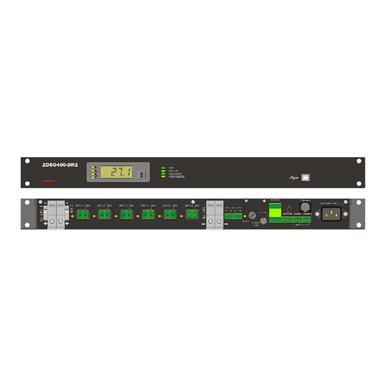
VAS modules separately: ZDSO400-DR2 for up to maximum 6 power amplifiers, cooperating with one or two battery banks. ZDSO400-DR4 for up to maximum 12 power amplifiers, cooperating with one to four battery banks. - Page 3 ZDSO400-DR2, ZDSO400-DR4 Document N . 0546.00.95-02.2 Page:3/18 ZDSO400-DR2 SIEĆ BATERIA ŁADOWANIE USZKODZENIE Fig.1. View and nominal dimensions of ZDSO400-DR2 power supplies. ZD SO 400-DR4 SIEĆ BAT ERIA ŁADOWANIE USZKODZENIE Fig.2. View and nominal dimensions of ZDSO400-DR4 power supplies.
- Page 4 6. Ferrite core, toroidal, insulted, dimensions: 22x13.7x6.3 F830 (6 pcs.). Fig.3. View of the front and back panel of the ZDSO400-DR2 power supply unit. A digital display panel, a USB port and 4 LED indication diodes are installed in the front panel of the...
- Page 5 ZDSO400-DR2, ZDSO400-DR4 Document N . 0546.00.95-02.2 Page:5/18 Fig. 4. View of the front and back panel of the ZDSO400-DR4 power supply unit A digital display panel, a USB port and 4 LED indication diodes are installed in the front panel of the...
-
Page 6: Operation Principle
Maximal current I for ZDSO400-DR2 is 6A, for PSU-24V-4 is 2x6A (two separated outputs 6A) – the value max a corresponds to the 6.3Amps fuses used. The listed range includes voltage values between the voltage of a discharged battery bank (at the end of the floating mode cycle) and the value of the bulk charging mode voltage, including temperature compensation. - Page 7 Bat fault Gen fault 230V 50-60Hz 230V 50Hz sensor POWER SUPPLY OUTPUTS FOR DSO MODULES REMOTE SYGNALLING OUTPUTS BATTERY CONNECTORS BATTERY CONNECTORS EXTERNAL DSO CONTROLLER POWER SUPPLY SYGNALLING INPUT 12V BATTERY 12V BATTERY Fig.5a Block diagram of ZDSO400-DR2 power supply.
- Page 8 ZDSO400-DR2, ZDSO400-DR4 Document N . 0546.00.95-02.2 Page:8/18 BATTERY CURRENT MEASUREMENT SYSTEM RECTIFIER 400W BATTERY VOLTAGE EQUALISATION SYSTEM 12V BATTERY 12V BATTERY LED SIGNALLING DIGITAL MEASUREMENT PANEL PANEL USB SOCKET Mains ZDSO400-DR4 Battery Charging Fault BATTERY CURRENT MEASUREMENT SYSTEM RECTIFIER 400W...
- Page 9 The circuit of the ZDSO400-DR2 or ZDSO400-DR4 power supply is equipped with a LVD – an internal switch of deep discharge implemented in the relays in their output circuits (one relay in each circuit for powering amplifiers and one at each double outputs for powering the VAS controller).
-
Page 10: Installation And Connection
Fig. 6. Mounting the ferrite cores on the DC cables to the amplifiers The ZDSO400-DR2 power supply is equipped with two power supply outputs for VAS controllers, while the ZDSO400-DR4 power supply unit is equipped with four such outputs. If the VAS system requires a higher number of controllers and cooperating devices to be used, corresponding splitting should be implemented outside the power supply unit. -
Page 11: First Start
4. First Start 4.1. The initial information The first start of the VAS system including the ZDSO400-DR2 or ZDSO400-DR4 and connected batteries should be done by qualified service personnel of the Manufacturer or the properly trained authorized personnel. - Page 12 ZDSO400-DR2, ZDSO400-DR4 Document N . 0546.00.95-02.2 Page:12/18 battery circuit. It is assumed the battery is connected if the measured resistance is lower than 2Ω. The resistance measurements of the battery circuits are conducted periodically and on such the basis the battery configuration change can be detected.
- Page 13 VAS modules. The voltage presence and its value should be checked by means of a voltmeter. In this state, the MAINS LED on the front panel of the ZDSO400-DR2 or ZDSO400-DR4 should be off and the FLT LED should be on.
-
Page 14: Operation
Inputs of external fault indications are located on the potential of negative bus of the battery bank. The interference filters used in the ZDSO400-DR2 in ZDSO400-DR4 power supplies are equipped with the Y class capacitors causing the appearance of the leakage current in the protective conductor of maximum 1.5 mA and 3mA in ZDSO400-DR4. - Page 15 ZDSO400-DR2, ZDSO400-DR4 Document N . 0546.00.95-02.2 Page:15/18 only when the reason triggering the indication is no longer present. The indication systems are reset automatically only when the mains power is restored and external signals at the EXT. FAULT 1 EXT.
-
Page 16: Servicing
ZDSO400-DR2, ZDSO400-DR4 Document N . 0546.00.95-02.2 Page:16/18 6. Servicing 6.1. Circuit breakers Fuse type circuit breakers are easily accessible for the service team. Their parameters have been specified in the table below. Fuse type and value of Fuse type and value... -
Page 17: Additional Information
ZDSO400-DR2, ZDSO400-DR4 Document N . 0546.00.95-02.2 Page:17/18 OŚ OBROTU PIVOT AXIS Fig.8. Access to the fuses in the 2U power supply version 6.2. Detecting faults and troubleshooting Most cases of malfunctions which can occur during device operation are indicated and handled by the microprocessor installed in the device. - Page 18 ZDSO400-DR2, ZDSO400-DR4 Document N . 0546.00.95-02.2 Page:18/18 External fault 2 short circuit on this input Rectifier-1 fault Rectifier-2 fault ( only in ZDSO400-DR4 Power failure OVERLOAD - battery loaded despite the mains present High battery voltage (higher than value set as parameters...
Need help?
Do you have a question about the ZDSO400-DR2 and is the answer not in the manual?
Questions and answers