Sign In
Upload
Manuals
Brands
Allied Telesis Manuals
Network Router
AT-AR4050S
Allied Telesis AT-AR4050S Manuals
Manuals and User Guides for Allied Telesis AT-AR4050S. We have
2
Allied Telesis AT-AR4050S manuals available for free PDF download: Installation Manual
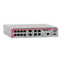
Allied Telesis AT-AR4050S Installation Manual (80 pages)
Brand:
Allied Telesis
| Category:
Network Router
| Size: 5 MB
Table of Contents
Table of Contents
5
Preface
11
Document Conventions
12
Contacting Allied Telesis
13
Chapter 1: Overview
15
Features
16
10/100/1000 Mbps Twisted Pair Ports
16
WAN Ports
16
USB Port
16
USB Retainer Slot
16
SD Card Slot
16
Reset Button
16
High Availability
16
Leds
16
Kensington Lock Hole
17
Installation Options
17
Management Software and Interfaces
17
Management Methods
17
Package Contents
18
Front and Back Panels
19
Figure 1: Front Panel of the AT-AR3050S Router
19
Figure 2: Front Panel of the AT-AR4050S Router
19
Figure 3: Back Panel of the AT-AR3050S and AT-AR4050S Routers
20
Management Panel
21
Figure 4: AT-AR3050S and AT-AR4050S Management Panel
21
Management Software
22
Twisted Pair Ports
23
WAN Ports
24
ETH Ports (RJ-45)
24
ETH Ports (SFP)
24
Bypass Ports
24
Leds
26
Power LED
26
Fault LED
26
Figure 5: Power LED
26
Table 1: Power LED
26
High Availability LED
27
Figure 6: Fault LED
27
Figure 7: HA LED
27
Table 2: Fault LED
27
Usb Led
28
Figure 8: USB LED
28
Table 3: High Availability LED
28
SD Card LED
29
Figure 9: SD Card LED
29
Table 4: USB LED
29
Leds for the ETH 1 and ETH 2 Ports (RJ-45)
30
Figure 10: ETH Port (RJ-45) Leds
30
Table 5: SD Card LED
30
Leds for the Twisted Pair LAN Ports
31
Table 6: Leds for ETH 1 and ETH 2 Ports (RJ-45)
31
Figure 11: Leds for the 10/100/1000Base-T Ports
32
Table 7: Leds for the Twisted Pair LAN Ports
32
Leds for the ETH 1 and ETH 2 Ports (SFP)
33
Function 1 LED
33
Figure 12: Leds for ETH 1 and ETH 2 Ports (SFP)
33
Table 8: Leds for ETH 1 and ETH 2 Ports (SFP)
33
Function 2 LED
34
Figure 13: Function 1 LED
34
Figure 14: Function 2 LED
34
USB Port
35
Figure 15: USB Port
35
USB Retainer Slot
36
Figure 16: USB Retainer Slot
36
Figure 17: USB Retainer
37
Figure 18: Attaching the USB Retainer
37
Figure 19: Attaching the Cable Tie
38
SD Card Slot
39
Figure 20: SD Card Slot
39
Console Port
40
Figure 21: Console Port
40
Reset Button
41
Figure 22: Reset Button
41
Power Supply
42
Chapter 2: Beginning the Installation
43
Reviewing Safety Precautions
44
Choosing a Site for the Routers
48
Unpacking the Router
49
Figure 23: Components of the AT-AR3050S and AT-AR4050S Routers
49
Chapter 3: Installing the Router and Powering on the Router
51
Figure 24: Power Cord Retaining Clip
52
Figure 25: Inserting the Retaining Clip into the Retaining Bracket
52
Installing the Router on a Table or Desktop
53
Figure 26: Attaching the Rubber Feet
54
Figure 27: Turning the Router Upside down
55
Figure 28: Removing the Rubber Feet
56
Figure 29: Attaching Handles to the Brackets
56
Figure 30: Attaching the Equipment Rack Brackets
57
Figure 31: Mounting the Router Horizontally in an Equipment Rack
57
Figure 32: Attaching the Wall Mount Brackets to the Side of the Router
59
Figure 33: Making the Anchor Hole Locations
60
Figure 34: Securing the Router to the Wall
61
Figure 35: Power Cord Retaining Clip in the up Position
62
Figure 36: Connecting the AC Power Cord
63
Figure 37: Connecting the Management Cable to the Console Port
64
Figure 38: Router Initialization Messages
65
Figure 39: Router Initialization Messages (Continued)
66
Chapter 4: Cabling the Networking Ports
67
Cabling the Twisted Pair Ports
68
Figure 40: Removing the Dust Plug from an SFP Slot
70
Figure 41: Installing an SFP Transceiver
71
Figure 42: Removing the Dust Cover from an SFP Transceiver
71
Figure 43: Positioning the SFP Handle in the Upright Position
72
Figure 44: Connecting a Fiber Optic Cable to an SFP Transceiver
72
Chapter 5: Troubleshooting
73
Appendix A: Technical Specifications
77
Physical Specifications
77
Environmental Specifications
77
Table 9: Product Dimensions
77
Table 10: Product Weights
77
Table 11: Environmental Specifications
77
Power Specifications
78
Certifications
78
Table 12: Maximum Power Consumptions
78
Table 13: Input Voltages
78
Table 14: Product Certifications
78
RJ-45 Twisted Pair Port Pinouts
79
Figure 45: RJ-45 Socket Pin Layout (Front View)
79
Table 15: Pin Signals for 10 and 100 Mbps
79
Table 16: Pin Signals for 1000 Mbps
79
RJ-45 Style Serial Console Port Pinouts
80
Table 17: RJ-45 Style Serial Console Port Pin Signals
80
Advertisement
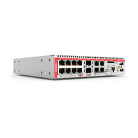
Allied Telesis AT-AR4050S Installation Manual (14 pages)
Rack Mount Installation Guide
Brand:
Allied Telesis
| Category:
Switch
| Size: 3 MB
Table of Contents
Table of Contents
5
Figure 1: Removing the Rubber Feet from the Device
10
Figure 2: Installing the Tray Chassis in a 19-Inch Equipment Rack
11
Figure 3: Pulling out the Tray
11
Figure 4: Aligning the Faceplate with the Edge of the Tray
12
Figure 5: Aligning the Faceplate 60Mm off the Edge of the Tray
13
Figure 6: Returning the Tray
13
Advertisement
Related Products
Allied Telesis AT-AR236E
Allied Telesis AT-AR256E
Allied Telesis AT-AR256E v3
Allied Telesis AT-ARW256E
Allied Telesis AT-AR221E
Allied Telesis AT-AR220E
Allied Telesis AT-AR240E
Allied Telesis AT-AR2010V
Allied Telesis AT-AR3050S
Allied Telesis AT-AR2050V
Allied Telesis Categories
Switch
Network Router
Media Converter
Network Hardware
Wireless Access Point
More Allied Telesis Manuals
Login
Sign In
OR
Sign in with Facebook
Sign in with Google
Upload manual
Upload from disk
Upload from URL