Allied Telesis AT-AR3050S Installation Manual
Hide thumbs
Also See for AT-AR3050S:
- Command reference manual (2425 pages) ,
- Installation manual (14 pages)
Table of Contents
Advertisement
Quick Links
Installation Guide
C613-04069-00 REV A
1
2
3
4
5
6
7
8
1
ETH
1000 LINK
ACT
100 LINK
ACT
1
2
3
4
5
6
7
8
1
ETH
1000 LINK
ACT
100 LINK
ACT
AT-AR3050S
AT-AR4050S
2
1
BYPASS
2
1
ETH
2
SD
CONSOLE
FAULT
PWR
USB
FNC1
HA
FNC2
READY
FAULT
FDX
HDX
COL
MASTER
STANDBY
2
1
2
1
ETH
2
SD
BYPASS
CONSOLE
FAULT
PWR
USB
FNC1
HA
FNC2
READY
FAULT
FDX
HDX
COL
MASTER
STANDBY
SD
READY
FAULT
CLASS 1
LASER PRODUCT
RESET
SD
READY
FAULT
CLASS 1
LASER PRODUCT
RESET
Advertisement
Table of Contents

Subscribe to Our Youtube Channel
Related Manuals for Allied Telesis AT-AR3050S


Summary of Contents for Allied Telesis AT-AR3050S
- Page 1 AT-AR3050S AT-AR4050S BYPASS READY FAULT CONSOLE FAULT CLASS 1 LASER PRODUCT FNC1 FNC2 RESET READY FAULT 1000 LINK 100 LINK MASTER STANDBY BYPASS READY FAULT CONSOLE FAULT CLASS 1 LASER PRODUCT FNC1 FNC2 RESET READY FAULT 1000 LINK...
- Page 2 Allied Telesis, Inc. has been advised of, known, or should have known, the...
- Page 3 Electrical Safety and Emissions Standards This product meets the following standards. U.S. Federal Communications Commission Radiated Energy Note: This equipment has been tested and found to comply with the limits for a Class A digital device pursuant to Part 15 of FCC Rules.
- Page 4 Translated Safety Statements Important: Safety statements that have the symbol are translated into multiple languages in the Translated Safety Statements document at www.alliedtelesis.com/support.
-
Page 5: Table Of Contents
Contents Preface ....................................11 Document Conventions .............................. 12 Contacting Allied Telesis ............................13 Chapter 1: Overview ................................. 15 Features ..................................16 10/100/1000 Mbps Twisted Pair Ports ........................ 16 WAN Ports ................................16 USB Port ................................16 USB Retainer Slot ............................... 16 SD Card Slot ............................... - Page 6 Contents Chapter 3: Installing the Router and Powering on the Router ..................51 Installing the Router on a Table or Desktop ....................... 53 Chapter 4: Cabling the Networking Ports ........................67 Cabling the Twisted Pair Ports ........................... 68 Chapter 5: Troubleshooting ............................. 73 Appendix A: Technical Specifications ...........................
- Page 7 Figure 1: Front panel of the AT-AR3050S router........................19 Figure 2: Front panel of the AT-AR4050S router........................19 Figure 3: Back panel of the AT-AR3050S and AT-AR4050S routers ...................20 Figure 4: AT-AR3050S and AT-AR4050S management panel ....................21 Figure 5: Power LED ................................26 Figure 6: Fault LED ................................27...
- Page 8 Figures...
- Page 9 Tables Table 1: Power LED ................................26 Table 2: Fault LED ................................27 Table 3: High Availability LED .............................28 Table 4: USB LED ................................29 Table 5: SD Card LED .................................30 Table 6: LEDs for ETH 1 and ETH 2 Ports (RJ-45) ......................31 Table 7: LEDs for the Twisted Pair LAN Ports ........................32 Table 8: LEDs for ETH 1 and ETH 2 ports (SFP) ........................33 Table 9: Product Dimensions ...............................77...
- Page 10 Tables...
-
Page 11: Preface
Preface This guide contains the installation instructions for the AT-AR3050S and AT-AR4050S routers. This preface contains the following sections: “Document Conventions” on page 10 “Contacting Allied Telesis” on page 11 ... -
Page 12: Document Conventions
Preface Document Conventions This document uses the following conventions: Note Notes provide additional information. Caution Cautions inform you that performing or omitting a specific action may result in equipment damage or loss of data. Warning Warnings inform you that performing or omitting a specific action may result in bodily injury. -
Page 13: Contacting Allied Telesis
Installation Guide for AT-AR3050S, AT-AR4050S Routers Contacting Allied Telesis If you need assistance with this product, you may contact Allied Telesis technical support by going to the Support & Services section of the Allied Telesis web site at www.alliedtelesis.com/support. You can find links for the following services on this page: 24/7 Online Support —... - Page 14 Preface...
-
Page 15: Chapter 1: Overview
Chapter 1 Overview This chapter contains the following sections: “Features” on page 12 “Package Contents” on page 14 “Front and Back Panels” on page 15 “Management Panel” on page 17 “Management Software” on page 18 “Twisted Pair Ports”... -
Page 16: Features
Chapter 1: Overview Features Here are the features of the AR3050S and AR4050S routers. 10/100/1000 Here are the basic features of the 10/100/1000 Mbps twisted pair ports. Mbps Twisted 8 LAN ports per router Pair Ports 10Base-T (IEEE 802.3i), 100Base-TX (IEEE 802.3u), and ... -
Page 17: Kensington Lock Hole
Installation Guide for AT-AR3050S, AT-AR4050S Routers High Availability LED USB LED SD card LED Duplex/collision and link/activity LEDs for the twisted pair ETH ports (RJ45) Duplex/collision and link/activity LEDs for the twisted pair LAN ports Link/activity LEDs for the ETH ports (SFP) ... -
Page 18: Package Contents
Chapter 1: Overview Package Contents 1 main unit 1 AC power cable 1 addendum document sheet 1 AC power cord retainer 1 USB retainer 1 double-side adhesive tape 2 cable ties 4 stick-on rubber feet kit ... -
Page 19: Front And Back Panels
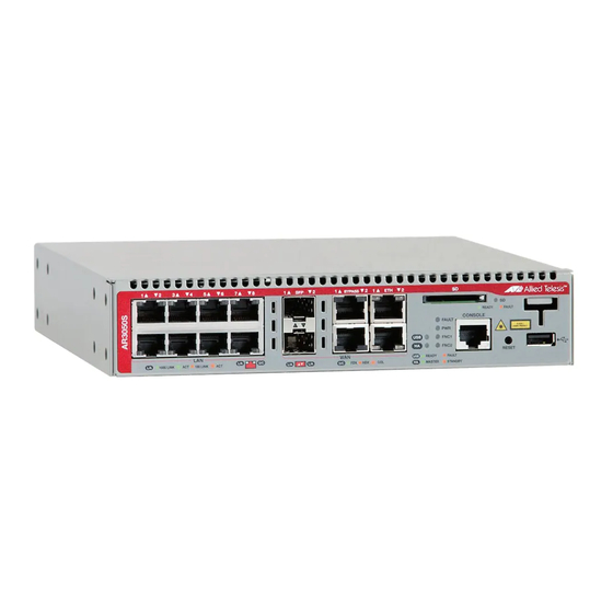
Installation Guide for AT-AR3050S, AT-AR4050S Routers Front and Back Panels The front panel of the AT-AR3050S router is shown in Figure 1. Intake Air Vents BYPASS READY FAULT CONSOLE FAULT CLASS 1 LASER PRODUCT FNC1 FNC2 RESET READY FAULT 1000 LINK... -
Page 20: Figure 3: Back Panel Of The At-Ar3050S And At-Ar4050S Routers
Chapter 1: Overview The back panel of the AT-AR3050S and AT-AR4050S routers is shown in Figure 3. Exhaust Air Vents Kensington Lock Hole On/Off switch AC INPUT 100-240V~ 50/60Hz 0.9A Power Cable Hook Mount Power Supply Figure 3. Back panel of the AT-AR3050S and AT-AR4050S routers... -
Page 21: Management Panel
Figure 4 identifies the components in the management panel on the AT- AR3050S and AT-AR4050S routers. USB Retainer Slot SD Card Slot Reset Button READY FAULT CONSOLE FAULT CLASS 1 LASER PRODUCT FNC1 FNC2 RESET READY FAULT MASTER STANDBY Console Port USB Port Figure 4. AT-AR3050S and AT-AR4050S management panel... -
Page 22: Management Software
Chapter 1: Overview Management Software The routers are shipped with the management software pre-installed. The software provides a Command Line Interface (CLI) and a Graphical User Interface (GUI) for in-band, over-the-network management. In the unlikely event that the management software becomes corrupted or damaged on the router, you can download the software from the Allied Telesis corporate web site and reinstall it on the router. -
Page 23: Twisted Pair Ports
Installation Guide for AT-AR3050S, AT-AR4050S Routers Twisted Pair Ports The AT-AR3050S and AT-AR4050S routers both feature 8 twisted pair LAN ports and 2 twisted pair ETH ports for WAN connection. All ports are 10Base-T, 100Base-TX, and 1000Base-T compliant. You can set the port speeds and duplex modes either automatically with IEEE 802.3u Auto-... -
Page 24: Wan Ports
Note SFP transceivers must be purchased separately. For a list of supported transceivers, contact your Allied Telesis distributor or reseller. Bypass Ports The routers have two bypass ports. You can use the bypass ports to connect the master router to backup routers to maintain the incoming WAN link. - Page 25 Installation Guide for AT-AR3050S, AT-AR4050S Routers link to the building and connect a bypass port of the master router to an ETH port of an identical backup router. The bypass port of the master router is only active and in the bypass mode if: The master router has no power supply or suffers an internal fault, ...
-
Page 26: Leds
Chapter 1: Overview LEDs Here are the descriptions of the LEDs. Power LED The Power LED reports the status of AC power. The LED is shown in Figure 5. READY FAULT CONSOLE FAULT CLASS 1 Power LED LASER PRODUCT FNC1 FNC2 RESET READY... -
Page 27: High Availability Led
Installation Guide for AT-AR3050S, AT-AR4050S Routers READY FAULT CONSOLE Fault LED FAULT CLASS 1 LASER PRODUCT FNC1 FNC2 RESET READY FAULT MASTER STANDBY Figure 6. Fault LED The LED is described in Table 2. Table 2. Fault LED State Description The router is operating normally. -
Page 28: Usb Led
Chapter 1: Overview The LED is described in Table 3. Table 3. High Availability LED State Description No HA-Mode VRRP (Virtual Router High Redundancy Protocol) instances are Availability configured on the router. Steady An HA-Mode VRRP instance on the router Green is in master state. -
Page 29: Sd Card Led
Installation Guide for AT-AR3050S, AT-AR4050S Routers The LED is described in Table 4. Table 4. USB LED State Description Memory No USB device is attached. Mode and Steady USB device is experiencing failure. Modem Yellow Mode Memory Steady USB storage device is mounted correctly. -
Page 30: Leds For The Eth 1 And Eth 2 Ports (Rj-45)
Chapter 1: Overview Table 5. SD Card LED State Description No SD card is attached. SD Card Steady SD card is attached and recognized. Green Blinking SD card activity is in read or write. Green Blinking SD card is experiencing failure. Yellow LEDs for the Each twisted pair port on the routers has two LEDs that display link,... -
Page 31: Leds For The Twisted Pair Lan Ports
A port has not established a link with another network device. LEDs for the Each twisted pair port on the AT-AR3050S and AT-AR4050S routers has two LEDs that display link, activity, duplex and collision information. The Twisted Pair LEDs are shown in Figure 11. -
Page 32: Figure 11: Leds For The 10/100/1000Base-T Ports
Chapter 1: Overview Duplex/Collision LED Link/Activity LED 1000 LINK 100 LINK Link/Activity LED Duplex/Collision LED Figure 11. LEDs for the 10/100/1000Base-T Ports The LEDs are described in Table 7. Table 7. LEDs for the Twisted Pair LAN Ports State Description Solid Green A port has established a 1000 Mbps link to a network device. -
Page 33: Leds For The Eth 1 And Eth 2 Ports (Sfp)
Installation Guide for AT-AR3050S, AT-AR4050S Routers Table 7. LEDs for the Twisted Pair LAN Ports State Description A port has not established a link with another network device. LEDs for the The LEDs for the ETH 1 and ETH 2 ports (SFP) are located between the slots, as shown in Figure 12. -
Page 34: Function 2 Led
Chapter 1: Overview READY FAULT CONSOLE FAULT CLASS 1 LASER PRODUCT Function 1 LED FNC1 FNC2 RESET READY FAULT MASTER STANDBY Figure 13. Function 1 LED Function 2 LED The Function 2 LED is shown in Figure 14. The Function 2 LED is user configurable and controlled by trigger actions. -
Page 35: Usb Port
Installation Guide for AT-AR3050S, AT-AR4050S Routers USB Port The management panel has a USB port which is shown in Figure 15. You may also use the port for the following maintenance purposes. Store configuration files on a USB device and copy the files to ... -
Page 36: Usb Retainer Slot
Chapter 1: Overview USB Retainer Slot The management panel has a USB retainer slot which is shown in Figure 16. You can use the USB retainer kit and the USB retainer slot to prevent the USB device from falling out the USB port. Note Cable ties are designed to be used only once. -
Page 37: Figure 17: Usb Retainer
Installation Guide for AT-AR3050S, AT-AR4050S Routers of the USB retainer as shown in Figure 17. Double-side adhesive tape USB retainer ring Stick Back of the USB retainer Cut to an appropriate size Figure 17. USB retainer 2. Mount the USB device into the USB port and then attach the H-shaped tip of the USB retainer to the USB retainer slot as shown in Figure 18. -
Page 38: Figure 19: Attaching The Cable Tie
Chapter 1: Overview E T H R EA D Y FA U LT C O N S O FA U LT P W R U S B F N C 1 CL AS S 1 LA SE R PR OD UC T F N C 2 R EA D Y FA U LT... -
Page 39: Sd Card Slot
Installation Guide for AT-AR3050S, AT-AR4050S Routers SD Card Slot The management panel has an SD card slot which is shown in Figure 20. You may use the port for the following maintenance purposes. Store configuration files on flash drives and restore the files to ... -
Page 40: Console Port
Chapter 1: Overview Console Port The Console port is used to establish a management session with the router to configure its features and parameter settings. The Console port is shown in Figure 21. This type of management uses serial RS-232 and is commonly referred to as local or out-of-band management because it is not conducted over your network. -
Page 41: Reset Button
Installation Guide for AT-AR3050S, AT-AR4050S Routers Reset Button The reset button is located between the Console port and the USB port. You may use the reset button to restore the router to its factory default settings or reboot the router. -
Page 42: Power Supply
Chapter 1: Overview Power Supply Each router has an internal power supply with a single AC power supply socket on the back panel. A power cable is supplied with the router. You can use the On/Off switch on the back panel of the router to power the router on or off. -
Page 43: Chapter 2: Beginning The Installation
Chapter 2 Beginning the Installation The chapter contains the following sections: “Reviewing Safety Precautions” on page 10 “Choosing a Site for the Routers” on page 14 “Unpacking the Router” on page 15 ... -
Page 44: Reviewing Safety Precautions
Chapter 2: Beginning the Installation Reviewing Safety Precautions Review the following safety precautions before beginning the installation procedure. Note Safety statements that have the symbol are translated into multiple languages in the Translated Safety Statements document at www.alliedtelesis.com/support. Warning Class 1 Laser product. - Page 45 Installation Guide for AT-AR3050S, AT-AR4050S Routers Warning Power cord is used as a disconnection device. To de-energize equipment, disconnect the power cord. E3 Warning Class I Equipment. This equipment must be earthed. The power plug must be connected to a properly wired earth ground socket outlet.
- Page 46 Chapter 2: Beginning the Installation Caution Risk of explosion if battery is replaced by an incorrect type. Replace only with the same or equivalent type recommended by the manufacturer. Dispose of used batteries according to the manufacturer’s instructions. Attention: Le remplacement de la batterie par une batterie de type incorrect peut provoquer un danger d’explosion.
- Page 47 Installation Guide for AT-AR3050S, AT-AR4050S Routers Caution The unit does not contain serviceable components. Please return damaged units for servicing. E42 Warning When you remove an SFP module from this product, the case temperature of the SFP may exceed 40° C (158° F). Exercise...
-
Page 48: Choosing A Site For The Routers
Chapter 2: Beginning the Installation Choosing a Site for the Routers Observe these requirements when planning the installation of the router. If you plan to install the routers in an equipment rack, check to be sure that the rack is safely secured so that it will not tip over. Devices in a rack should be installed starting at the bottom, with the heavier devices near the bottom of the rack. -
Page 49: Unpacking The Router
Installation Guide for AT-AR3050S, AT-AR4050S Routers Unpacking the Router Figure 1 lists the items that come with the AT-AR3050S and AT-AR4050S routers. If any item is missing or damaged, contact your Allied Telesis sales representative for assistance. You should retain the original packaging material in the event you need to return the unit to Allied Telesis. - Page 50 Chapter 2: Beginning the Installation...
-
Page 51: Chapter 3: Installing The Router And Powering On The Router
“Installing the Router on a Wall” on page 25 “Connecting AC Power to a Power Supply Module” on page 28 “Monitoring the Initialization Processes” on page 31 Note The procedures apply to both the AT-AR3050S and AT-AR4050S routers. -
Page 52: Figure 24: Power Cord Retaining Clip
Chapter 3: Installing the Router and Powering on the Router Installing the Power Cord Retaining Clip Perform the following procedures to install the power cord retaining clip on the power supply module. Warning Power cord is used as a disconnection device. To de-energize equipment, disconnect the power cord. -
Page 53: Installing The Router On A Table Or Desktop
Installation Guide for AT-AR3050S, AT-AR4050S Routers Installing the Router on a Table or Desktop You may install the routers on a table or desktop. Here are the guidelines to selecting a site. The table should be level and stable. ... -
Page 54: Figure 26: Attaching The Rubber Feet
Chapter 3: Installing the Router and Powering on the Router Fitting Rubber Feet If your routers do not already have rubber feet fitted, fit these as follows: 1. Remove all equipment from the package and store the packaging material in a safe place. 2. -
Page 55: Figure 27: Turning The Router Upside Down
14. Here is the procedure for installing the routers in a 19-inch equipment rack. Caution The chassis may be heavy and awkward to lift. Allied Telesis recommends that you get assistance when mounting the chassis in an equipment rack. E28 1. -
Page 56: Figure 28: Removing The Rubber Feet
Chapter 3: Installing the Router and Powering on the Router Figure 5. Turning the router upside down 2. If rubber feet are attached to the base of the router, remove them by prising off with a flat-head screwdriver, as shown in Figure 6, then turn the router back over. -
Page 57: Figure 30: Attaching The Equipment Rack Brackets
Installation Guide for AT-AR3050S, AT-AR4050S Routers 4. Use the four handle screws to screw the handles to the wider side of each bracket, as show in Figure 7. Figure 7. Attaching handles to the brackets 5. Use the eight bracket screws to screw the two rack mount brackets to the sides of the router, as shown in Figure 8. - Page 58 Chapter 3: Installing the Router and Powering on the Router Figure 9. Mounting the router horizontally in an equipment rack 7. Go to Chapter 4, “Cabling the Networking Ports” on page 37, to connect the network cables to the ports on the router.
-
Page 59: Figure 32: Attaching The Wall Mount Brackets To The Side Of The Router
Installation Guide for AT-AR3050S, AT-AR4050S Routers Installing the Router on a Wall This procedure requires the following items: A wall mount kit (not provided) Two equipment rack brackets (not provided) Cross-head screwdriver (not provided) If you are fixing the routers to a solid masonry or hollow wall, you ... -
Page 60: Figure 33: Making The Anchor Hole Locations
Chapter 3: Installing the Router and Powering on the Router 4. Have another person hold the router at the wall location where the router is to be installed, while you use a pencil or pen to mark the wall with the locations of the holes in the brackets. The router should be oriented such that its front faceplate is facing to the left or right, and is vertically level. -
Page 61: Figure 34: Securing The Router To The Wall
Installation Guide for AT-AR3050S, AT-AR4050S Routers 6. While another person holds the router at the wall location, secure it to the wall using the 16 wall mounting screws. See Figure 12. Figure 12. Securing the router to the wall... -
Page 62: Figure 35: Power Cord Retaining Clip In The Up Position
See Figure 3 on page 16 for the location of the intake air vents. Warning On both the AT-AR3050S and AT-AR4040S routers, keep the intake vents clear of any obstructions to insure proper cooling of the router components. -
Page 63: Figure 36: Connecting The Ac Power Cord
Installation Guide for AT-AR3050S, AT-AR4050S Routers Warning Power cord is used as a disconnected device. To de-energize equipment, disconnect the power cord. E3 I N P 1 0 0 - 2 4 0 5 0 / 6 0 H z 0 . -
Page 64: Figure 37: Connecting The Management Cable To The Console Port
Chapter 3: Installing the Router and Powering on the Router Starting a Local Management Session This procedure requires a terminal or a terminal emulator program and the management cable that comes with the router. To start a local management session on the router, perform the following procedure: 1. -
Page 65: Figure 38: Router Initialization Messages
Installation Guide for AT-AR3050S, AT-AR4050S Routers Monitoring the Initialization Processes It takes about thirty seconds for the router to initialize its management software programs and features, and load the default configuration. You may also monitor the bootup sequence by connecting a terminal or computer that has a terminal emulator program, to the console port on the router. -
Page 66: Figure 39: Router Initialization Messages (Continued)
Chapter 3: Installing the Router and Powering on the Router Checking system reboot stability... Starting base/cron... Starting base/appmond... Starting hardware/openhpi... Starting hardware/timeout... Starting base/inet... Starting base/modules... Received event modules.done Received event board.inserted Received event hardware.done Starting network/startup... Starting base/external-media... Starting network/roboswitch... Received event network.enabled Initializing HA processes: auth, hostd, hsl, irdpd, lacp, loopprot, mstp... -
Page 67: Chapter 4: Cabling The Networking Ports
Chapter 4 Cabling the Networking Ports This chapter contains the following procedures: “Cabling the Twisted Pair Ports” on page 38 “Installing Optional SFP Transceivers” on page 40 ... -
Page 68: Cabling The Twisted Pair Ports
Chapter 4: Cabling the Networking Ports Cabling the Twisted Pair Ports Here are the guidelines to cabling the 10/100/1000Base-T twisted pair ports. The connectors on the cables should fit snugly into the ports, and the tabs should lock the connectors into place. The default setting for the wiring configurations of the ports is auto- ... - Page 69 Installation Guide for AT-AR3050S, AT-AR4050S Routers support Auto-Negotiation and have a fixed duplex mode. You should disable Auto-Negotiation on those ports and set their duplex modes manually to avoid the possibility of duplex mode mismatches. A router port using Auto-Negotiation defaults to half-...
-
Page 70: Figure 40: Removing The Dust Plug From An Sfp Slot
Chapter 4: Cabling the Networking Ports Installing Optional SFP Transceivers Review the following guidelines before installing SFP transceivers in the router. The transceiver can be hot-swapped; you do not need to power off the router to install a transceiver. However, always remove the cables before removing the transceiver. -
Page 71: Figure 41: Installing An Sfp Transceiver
3. If you are installing the transceiver in a top slot, position the transceiver with the Allied Telesis label facing up. If you are installing the transceiver in a bottom slot, position the transceiver with the label facing down. -
Page 72: Figure 43: Positioning The Sfp Handle In The Upright Position
Chapter 4: Cabling the Networking Ports 6. Verify the position of the handle on the SFP transceiver. If the transceiver is in a top slot, the handle should be in the upright position, as shown in Figure 21. If the transceiver is in a bottom slot, the handle should be in the down position. -
Page 73: Chapter 5: Troubleshooting
This chapter contains suggestions on how to troubleshoot the router if a problem occurs. Note For further assistance, please contact Allied Telesis Technical Support at www.alliedtelesis.com/support. Problem 1: The POWER LED on the front of the router is off. Solutions: The unit is not receiving power. Try the following: Verify that the power cord is securely connected to the power ... - Page 74 Chapter 5: Troubleshooting then the problem is with the cable or the other network device. Verify that the twisted pair cable does not exceed 100 meters (328 feet). Verify that you are using the appropriate category of twisted pair ...
- Page 75 Installation Guide for AT-AR3050S, AT-AR4050S Routers Negotiation is connected to a device with a fixed duplex mode of full duplex. If this is the cause of the problem, adjust the duplex mode of the port on the network device or on the router so that both ports are using the same duplex mode.
- Page 76 Chapter 5: Troubleshooting...
-
Page 77: Appendix A: Technical Specifications
Technical Specifications Physical Specifications Dimensions (H x W x D) Table 1. Product Dimensions AT-AR3050S 42.5 mm x 210 mm x 220 mm (1.7 in. x 8.3 in. x 8.7 in.) AT-AR4050S 42.5 mm x 210 mm x 220 mm (1.7 in. -
Page 78: Power Specifications
Appendix A: Technical Specifications Power Specifications Maximum Power Consumptions Table 4. Maximum Power Consumptions AT-AR3050S 20 watts AT-AR4050S 20 watts Input Voltages Table 5. Input Voltages AT-AR3050S 100-240 VAC, 0.9 A maximum, 50/ 60 Hz per input AT-AR4050S 100-240 VAC, 0.9 A maximum, 50/... -
Page 79: Rj-45 Twisted Pair Port Pinouts
Installation Guide for AT-AR3050S, AT-AR4050S Routers RJ-45 Twisted Pair Port Pinouts Figure 18 illustrates the pin layout of the RJ-45 connectors and ports. Figure 18. RJ-45 Socket Pin Layout (Front View) Table 7 on page 35 lists the pin signals for 10 and 100 Mbps. -
Page 80: Rj-45 Style Serial Console Port Pinouts
Appendix A: Technical Specifications Table 8. Pin Signals for 1000 Mbps (Continued) Pair 3 - Pair 2 - Pair 4 + Pair 4 - RJ-45 Style Serial Console Port Pinouts Table 9 lists the pin signals of the RJ-45 style serial Console port. Table 9.
Need help?
Do you have a question about the AT-AR3050S and is the answer not in the manual?
Questions and answers