Table of Contents
Advertisement
Quick Links
20____
Year of Manufacture:
Serial Number:
VTX
(Please log your machine's serial number and date of purchase for future reference.)
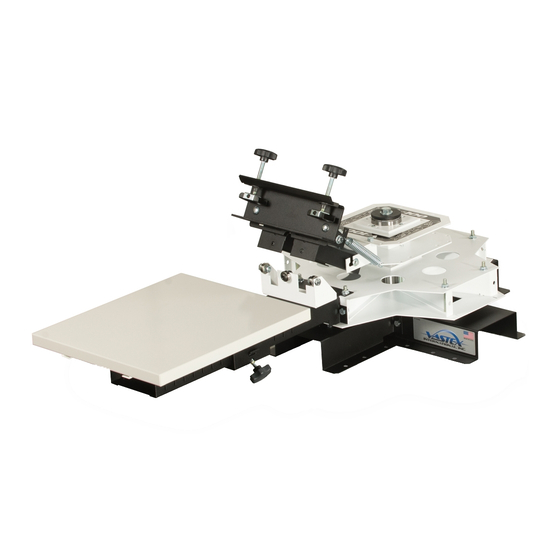
V-100
Machine Manual
Pg #
2-3
4-5
6
7
8
9
10-11
12-13
14
15
/
/
Date:____
____
______
Original Instructions
Vastex E-mail assistance
Purchasing & Product Information:
info@dalesway.co.uk
Andrew Stocking
0845 224 1204
Doc. # 01-26-001A
Advertisement
Table of Contents

Related Manuals for VASTEX V-100


Summary of Contents for VASTEX V-100
-
Page 1: Table Of Contents
C-Hub Assembly Center Assembly Rotor Arm Assembly Pallet Assembly 10-11 Print Head Assembly 12-13 Vastex E-mail assistance Machine Adjustments Purchasing & Product Information: Warranty info@dalesway.co.uk Andrew Stocking Date:____ ____ ______ Serial Number: 0845 224 1204... -
Page 2: Introduction / Safety / Features
Thank you for purchasing your printing equipment form Vastex International Inc. Vastex has been designing and building printing equipment since 1960. We have knowledge and experi- ence, and are proud to supply the printing industry with quality equipment at an affordable price. You can be confident your purchase will give you years of trouble free service. - Page 3 In the unlikely event that a part of your press breaks, or if your press does not seem to be operating normally and the instructions in this manual do not correct the issue, do not continue using your press. Contact Vastex for as- sistance in repairing your press.
-
Page 4: Stand Assembly
Stand Assembly Line up Notches Install and Leave Loose -(4) 5/16-18 x 3/4” Bolts -(4) 5/16-18 Lock Nuts Do not tighten until STEP 5 Slot Slot Wiggle shaft back and forth to Install and Tighten insert. Very tight fit. -(1) 1/2-13 x 1.0” Bolt -(1) 1/2”... - Page 5 Detent Installation Install (2) Detent Assemblies Slot Insert tab into slot in base. Rotate into position. Install 2 springs per Detent Pg.5...
-
Page 6: Rotor Hub Assembly
Rotor Hub Assembly Install and Leave Loose -(8) 5/16-18 x 3.0” Bolts -(8) 5/16-18 Lock Nuts 2) Install and leave loose -(8) 5/16-18 x 3.0” bolts -(8) 5/16-18 lock nuts For 1 station, tighten 3 sets. For 4 station, leave all outer bolts loose. Using 1/2”... -
Page 7: C-Hub Assembly
C-Hub Assembly Install and Leave Loose -(2) 5/16-18 x 2-1/4” Bolts -(2) 5/16-18 Lock Nuts Install all included hinges at this time Do Not Tighten until Hub Installation Step 3 Slot Slot 1 color Hub Shown Below 4 color Hub Shown Below Pg.7... -
Page 8: Center Assembly
Hub Installation 1/2-20 x 1.0” Bolt 1/2” Washer Large Washer(2x) Bearing Bearing Race 1) Bearings can only be installed in one di- rection, They must fit into the Bearing Bearings (2x) Race in each Hub. NOTE: Assembly shows 4 hinges on C-Hub. Your assembly may have from 1 to 4 Hinges depending on machine specs. -
Page 9: Rotor Arm Assembly
Rotor Arm Installation Install and tighten Remove -(4) 5/16-18 x 1/2” Bolts -(2) 5/16-18 Nuts for each Rotor -(4) 5/16-18 Lock Nuts Arm to be installed. Using 1/2” or 13mm Wrench Align Rotor Arm with Bolts in Rotor Hub. Tabs on bottom of Rotor Arm drop into slots in Bottom Rotor Hub Plate. -
Page 10: Pallet Assembly
Pallet Assembly Install and Tighten 2) Install -(4) 5/16-18 x 1/2” Bolts -(1)5/16-18 T Weldnut -(4) 5/16-18 Lock Nuts -(1)Pallet Arm knob Using 1/2” or 13mm wrench 4) Install Angel Clip Insert Corner Clamp Bracket Install 6) Install and Tighten -(1) Assembled Pallet Arm -(4) 5/16-18 x 1.0”... - Page 11 Pallet Installation Slide your assembled Pallet and Pallet Arm onto Rotor Arm. Set each pallet the same. Use slots on side of Rotor Arm for reference. Tighten knob on Pallet Arm. Do not over tighten. Pg.11...
-
Page 12: Print Head Assembly
Print Head Assembly Install and Tighten -(4) 5/16-18 x 3/4” Bolts -(2) 5/16 Flat Washers -(2) Double 5/16-18 Nuts -(1) Screen Clamp Mount Using 1/2” or 13mm Wrench Install and Tighten -(2) 5/16-18 x 3/4” Carriage Bolts -(2) 5/16 Flat Washers -(2) 5/16-18 Lock Nuts -(1) Assembled Screen Clamp Using 1/2”... - Page 13 Print Head Installation Note Spring Location Options/Orientation Normal Heavy Extra Heavy Attach Springs Install Print heads as shown. Attach Springs Install Stop Bar as shown. Stop Bar must be installed while head is in the Down position. Pg.13...
-
Page 14: Machine Adjustments
Machine Adjustments To Adjust Screen Height and an- gle Left to Right. Loosen (1) Nut (Marked A) Slightly and Set Screen Level. Adjust one side at a time. 1/2” or 13mm Wrench needed. To Adjust Screen angle Front to Back. Loosen (2) Bolts (Marked B) Slightly and Set Screen Level. -
Page 15: Warranty
The defective part or parts will be repaired or replaced at the discretion of Vastex International, Inc. If the equipment in question is less than one (1) year old, it will be shipped to the customer at no charge, with an RGA issued by Vastex for the defective part. The defective part must be shipped back to Vastex freight prepaid within 30 days or the account will be billed.
Need help?
Do you have a question about the V-100 and is the answer not in the manual?
Questions and answers