Table of Contents
Advertisement
Quick Links
Advertisement
Table of Contents

Summary of Contents for Tempo Communications OPM210
- Page 1 INSTRUCTION MANUAL OPM210 • OPM220 Fiber Optic Power Meter Read and understand all of the instructions and safety information in this manual before operating or servicing this tool. Register this product at www.TempoCom.com 55500197 REV11 © 2020 Tempo Communications Inc. 02/20...
-
Page 2: Table Of Contents
Table of Contents Description ..................3 Safety ..................... 3 Purpose of This Manual ..............3 Important Safety Information ............4-6 Introduction ..................7 Model Designations ..............7 Unpacking and Inspection ............7 Specifications ................. 8 General Information ..............9-12 Battery ..................9 Auto Power Off ................ -
Page 3: Description
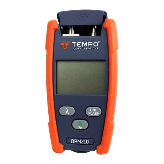
1625 nm between a power range of +6 to -70dBm. The OPM210 is supplied standard with a universal 2.5mm bulkhead. The OPM210 is supplied with a 1mW Visual Fault Locator that is used to measure fiber breaks, discontinuities and Macrobends. The VFL has a universal 2.5mm interface with an optional 1.25mm adapter... -
Page 4: Important Safety Information
Important Safety Information SAFETY ALERT SYMBOL This symbol is used to call your attention to hazards or unsafe practices which could result in an injury or property damage. The signal word, defined below, indicates the severity of the hazard. The message after the signal word provides information for preventing or avoiding the hazard. - Page 5 DO NOT STARE INTO BEAM CLASS 2 LASER PRODUCT The OPM210 and OPM220 instrument has a laser device, a Visual Fault Locator (VFL) conforming to the requirements of CDRH, CFR 1040, Subchapter J. While there is no potential for eye damage due to unaided direct exposure, users should always avoid looking directly into the output port.
- Page 6 Important Safety Information Electric shock hazard: • Do not insert batteries with the polarity reversed. • Do not open the case of the unit for any reason. It contains no user-serviceable parts. • Use this unit for the manufacturer’s intended purpose only, as described in this manual.
-
Page 7: Introduction
For recycling information, go to www.TempoCom.com. For recycling information, go to www.TempoCom.com. All specifications are nominal and may change as design improvements occur. Tempo Communications Inc. shall not be liable for damages resulting from misap- plication or misuse of its products. -
Page 8: Specifications
Specifications Model OPM210 OPM220 Measurement Range +6dBm to -70dBm -50dBm (1310/1490/1550/1625) (1310/1490/1550/1625) +6dBm to -60dBm (850/1300) +26 to -40dBm (850/1300) Calibrated Wavelengths 850, 1300, 1310, 1490, 1550, 1625nm Display Resolution 0.01dB Accuracy* +/-0.25dB Linearity* +/-0.5dB (+10 to -3dBm) +/-0.5dB +26 to -3dBm +/-0.1dB (-3 to -50dBm) -
Page 9: General Information
This section provides general instructions on how to use the instruments. Battery The OPM210 and OPM220 are powered with two AAA alkaline batteries. Do not use rechargeable batteries. When the battery power is low the low battery indicator will be displayed on the LCD. -
Page 10: Battery Installation Or Replacement
Battery To replace the batteries, follow these steps: Turn instrument off. Remove battery cover. Install the new batteries observing correct polarity as below. Connector Interface Both the OPM and VFL ports are universal 2.5mm. A 1.25mm adapter is available as an optional accessory. Cleaning the OPM and VFL Interfaces Make sure that the instrument is powered off. -
Page 11: Fn-Function Change
OPM Connector LED Light VFL Connector Set/Ref Set OPM Unit Set / Ref Set Power on/off and Function Fn—Function Change Press the “Fn” key to select OPM or VFL or LED function:... -
Page 12: Opm Mode
OPM Mode Press “λ” to select the wavelength. Press “Unit Flash” to change the unit dBm or dB. Press “Unit Flash” for two seconds for REF setting. Press “Unit Flash” and “λ” keys to reference 0dBm. VFL Mode Press “Unit Flash” to change output mode, 2Hz modulation or continuous. -
Page 13: Warranty
Limited Warranty Tempo Communications Inc. warrants to the original purchaser of these goods for use that these products will be free from defects in workmanship and material for one year, excepting normal wear and abuse. For all Test instrument repairs, you must first request a Return...


Need help?
Do you have a question about the OPM210 and is the answer not in the manual?
Questions and answers