Table of Contents
Advertisement
Quick Links
Advertisement
Table of Contents

Related Manuals for Tempo Communications 930XC-20C


Summary of Contents for Tempo Communications 930XC-20C
- Page 1 930XC-20C • 930XC-20M 930XC-30F • 930XC-30P Handheld OTDRs Read and understand all of the instructions and safety information in this manual before operating or servicing this tool. Register this product at www.TempoCom.com 52079877 REV 1 © 2020 Tempo Communications Inc. 01/20...
-
Page 2: Table Of Contents
930XC-20C • 930XC-20M • 930XC-30F • 930XC-30P Table of Contents Preface Description ..........................5 Safety ............................. 5 Purpose of This Manual ......................5 Warranty ..........................5 Important Safety Information Section 1. Introduction Section 2. Basic Operation Instrument Interface Description .................... 10 Use of Batteries ........................10 Auto Off Mode ........................ - Page 3 930XC-20C • 930XC-20M • 930XC-30F • 930XC-30P Delete File ........................22 Format Memory ....................... 23 Time Configuration ......................23 Auto Off Configuration ..................... 23 Language Configuration ....................24 Contrast Adjustment of LCD .................... 24 Color Mode Setting......................24 Default Setting ........................ 25 Help ..........................
- Page 4 930XC-20C • 930XC-20M • 930XC-30F • 930XC-30P Before Cleaning ........................39 Cleaning Interfaces and Connectors ..................39 Tools for Cleaning Interfaces and Connectors ..............39 Prrocedure for Cleaning Interfaces and Connectors .............. 39 Section 6. Specifications Stabilized Laser Source Module ..................41 Optical Power Meter Module ....................
-
Page 5: Preface Description
Warranty Tempo Communications Inc. warrants to the original purchaser of these goods for use that these products will be free from defects in workmanship and material for one year. This warranty is subject to the same terms and conditions contained in Tempo Communication’s standard one-year limited warranty. -
Page 6: Important Safety Information
930XC-20C • 930XC-20M • 930XC-30F • 930XC-30P Important Safety Information SAFETY ALERT SYMBOL This symbol is used to call your attention to hazards or unsafe practices which could result in an injury or property damage. The signal word, defined below, indicates the severity of the hazard. - Page 7 930XC-20C • 930XC-20M • 930XC-30F • 930XC-30P Important Safety Information (cont’d) Electric shock hazard: • Fuse replacement should be performed by Tempo qualified personnel. • Do not use repaired fuses or short-circuited fuse holders. Failure to observe these warnings could result in severe injury or death.
- Page 8 930XC-20C • 930XC-20M • 930XC-30F • 930XC-30P Important Safety Information (cont’d) Electric shock hazard: • Do not expose batteries to fire or intense heat. Do not open or mutilate batteries. Avoid touching the electrolyte in the batteries, which is corrosive and may cause damage to eyes or skin.
-
Page 9: Section 1. Introduction
930XC-20C • 930XC-20M • 930XC-30F • 930XC-30P Section 1. Introduction Tempo’s 930XC handheld OTDRs can make an assessment of one single optical fiber or a whole optical fiber chain. In addition, the user can directly observe loss and events distribution of an optical fiber chain. -
Page 10: Section 2. Basic Operation
powering on in order to protect the batteries in case of excessive discharging. The internal battery should be recharged immediately through the adapter. Recharging 930XC-20C • 930XC-20M • 930XC-30F • 930XC-30P Instruction Manual • Perform a quick charge first, and then switch to trickle charge after the voltage reaches a predefined figure. Quick charge temperature is 5 °C to 45 °C (41 °F to 113 °F), and trickle charge temperature is 0 °F to 55 °C (32 °F to 131 °F). -
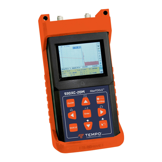
Page 11: Keypad Functions
930XC-20C • 930XC-20M • 930XC-30F • 930XC-30P Keypad Functions Figure 2-2. 930XC Keypad 1. On/Off: Press to turn power on or off to the instrument. 2. Run/Stop: • Under GUI, press to start measurement. • While testing, press to stop measurement. 3. Enter: • Under GUI, press to confirm the current operation. -
Page 12: Section 3. Basic Otdr Information
930XC-20C • 930XC-20M • 930XC-30F • 930XC-30P Section 3. Basic OTDR Information Principle of OTDRs An OTDR (Optical Time Domain Reflectometer) is a measurement instrument for identifying optical fiber transmission features. The OTDR is used to measure the overall attenuation of a fiber optic link and to provide details relating to the position of each event in that link. -
Page 13: Measurement Application
930XC-20C • 930XC-20M • 930XC-30F • 930XC-30P When some pulse energy is scattered, reflection events occur. When reflection events occur, a peak is displayed on the trace (Figure 3-1). Measurement Application The 930XC instruments display power relating to the distance of returning signals. This information can be used to identify the main properties of an optical fiber chain. -
Page 14: Information Window
930XC-20C • 930XC-20M • 930XC-30F • 930XC-30P The trace of the 930XC displays measurement results in a graphic form. The y-axis represents the power while the x-axis represents the distance (Figure 3-4). Information Window The contents of this window are measurement parameters, events list, marker A/B, and analysis parameters. -
Page 15: Marker A/B Information
930XC-20C • 930XC-20M • 930XC-30F • 930XC-30P • Attn.: Attenuation characteristic from one event point to the current event. • Cum.L.: Cumulative loss, calculating from beginning point to the current event. Figure 3-7. Marker A/B Information Marker A/B Information A marker is used to mark and analyze a single event, trace section, and distance. Distance, attenuation, and loss at a marker or between markers will be displayed in marker information (Figure 3-7). -
Page 16: Menu Bar And Icons
930XC-20C • 930XC-20M • 930XC-30F • 930XC-30P Fiber Information Fiber information includes total attenuation, length, and loss of the tested fiber (Figure 3-8). Icons Description Parameter configuration Save file Open file Re-analyze the trace Zoom out trace horizontally Zoom in trace horizontally... -
Page 17: Definitions Of Measurement Parameters
930XC-20C • 930XC-20M • 930XC-30F • 930XC-30P Definitions of Measurement Parameters Range Pulse Width Average Time Select suitable testing time Wavelength Select laser wavelength for measurement Measurement Mode Select mode for measurement PM/LS Optical power meter, stabilized laser source, and VFL... -
Page 18: Pulse Width Configuration
930XC-20C • 930XC-20M • 930XC-30F • 930XC-30P Pulse Width Configuration The selection of pulse width affects the dynamic range and resolution of the measurement. With a narrow pulse width there will be higher resolution and smaller deadzone; however, the dynamic range will be decreased. A wide pulse width will bring higher dynamic range and measure comparatively longer distance, but resolution and deadzone will be increased. -
Page 19: Measurement Mode Configuration
930XC-20C • 930XC-20M • 930XC-30F • 930XC-30P Figure 3-13. Wavelength Configuration Measurement Mode Configuration There are two kinds of measurement mode: averaging and realtime. Under realtime mode the 930XC will undertake realtime measurement for the connector of exterior fiber and refurbish the measured trace. While under realtime mode, press Run/Stop to stop;... -
Page 20: Length Units
930XC-20C • 930XC-20M • 930XC-30F • 930XC-30P Length Units Under the parameter configuration menu use p and q to highlight “Length Units.” Press Enter to select the desired units of measurement (Figure 3-16). Press to exit. Figure 3-16. Length Units... -
Page 21: Non-Reflection Threshold Configuration
930XC-20C • 930XC-20M • 930XC-30F • 930XC-30P Press to exit. Use t and u to adjust the position of the highlighted area. Use p and q to change the digits. After setting, press Enter to confirm. Non-reflection Threshold Configuration This configuration has direct impact on the listing of insertion loss events. Only events ≥ to this threshold will be listed. -
Page 22: End Threshold Configuration
930XC-20C • 930XC-20M • 930XC-30F • 930XC-30P End Threshold Configuration This threshold is the end threshold of optical fiber. If the end threshold equals 3.0 dB, then the first event with insertion loss ≥ 3 dB will be considered the end of the optical fiber. If the value is set to 0 dB, there will be no end threshold. -
Page 23: Format Memory
930XC-20C • 930XC-20M • 930XC-30F • 930XC-30P Format Memory Press format memory to format the internal memory. Figure 3-22a. Format Memory Time Configuration Time configuration is used to change system time. Under the parameter configuration menu use p and q to highlight “Time (y-m-d).” Press Enter to change (Figure 3-23). -
Page 24: Language Configuration
930XC-20C • 930XC-20M • 930XC-30F • 930XC-30P Under the parameter configuration menu use p and q to highlight “Auto Off.” Press Enter to switch between “Off” and “On” (Figure 3-24). Press to exit. Note: The default setting is “On.” Language Configuration Figure 3-25. -
Page 25: Default Setting
930XC-20C • 930XC-20M • 930XC-30F • 930XC-30P Under the parameter configuration menu use p and q to highlight “Color Mode.” Press Enter to choose a different mode (Figure 3-27). Press to exit. Use p and q to highlight the desired color mode setting. Press Enter to confirm the selection. -
Page 26: Battery Recharge Status
930XC-20C • 930XC-20M • 930XC-30F • 930XC-30P Battery Recharge Status When the 930XC is powered off and powered through the AC/DC adapter, the “CHARGE” indicator on the interface panel (Figure 2-1) will be lit. When the battery is fully recharged, the indicator will turn off. -
Page 27: Section 4. Trace Measurement And Processing Of Existing Traces
930XC-20C • 930XC-20M • 930XC-30F • 930XC-30P Section 4. Trace Measurement and Processing of Existing Traces Graphical User Interface (GUI) Instructions When the 930XC is first turned on, an introductory screen appears on the LCD (Figure 4-1). 930XC-XXX Figure 4-1. Power On Screen Three seconds after the instrument is turned on, a quick reference screen appears (Figure 4-2). -
Page 28: Setup
930XC-20C • 930XC-20M • 930XC-30F • 930XC-30P Setup Connect the optical fiber directly to the 930XC optic output. No tools are required. • Clean the connectors. Refer to Section 5 of this manual for details. • Clean the tie-ins, making sure they are compatible (APC or UPC). -
Page 29: Manual Trace Measurement
930XC-20C • 930XC-20M • 930XC-30F • 930XC-30P Manual Trace Measurement To achieve optimal measurement results, set the parameters manually. 1. Set the range. Refer to “Range Configuration” in Section 3. 2. Press Run/Stop to start the measurement. The process is the same as with auto measurement. -
Page 30: Information Between Marker A/B
930XC-20C • 930XC-20M • 930XC-30F • 930XC-30P Information between Marker A/B Under GUI (Figure 4-4) press to switch information window to marker A/B information. Use t and u to move marker A or B. Zoom a Trace Zoom out Trace Horizontally To review the details of an event more closely, follow these steps: 1. -
Page 31: Browse Saved Traces
930XC-20C • 930XC-20M • 930XC-30F • 930XC-30P 2. Input file name: Use p, q, t, and u to choose the alphanumeric characters one by one, and then press Enter to confirm. The filename can be a maximum of eight characters in length. -
Page 32: Power Meter, Laser Source, And Vfl Settings
930XC-20C • 930XC-20M • 930XC-30F • 930XC-30P Power Meter, Laser Source, and VFL Settings Optical Power Meter Settings 1. Enter PM/LS interface as described in “Power Meter, Laser Source, and VFL Configuration” in Section 3. Use p and q to highlight “OPM”, and press Enter to enter OPM interface (Figure 4-10) -
Page 33: Stabilized Laser Source Settings
930XC-20C • 930XC-20M • 930XC-30F • 930XC-30P Stabilized Laser Source Settings 1. Enter PM/LS interface as described in “Power Meter, Laser Source, and VFL Configuration” in Section 3. Use p and q to highlight “SLS”, and press Enter to enter SLS interface (Figure 4-12). -
Page 34: Link Viewer
930XC-20C • 930XC-20M • 930XC-30F • 930XC-30P 2. Use t and u to toggle between VFL working modes. Press Enter to enter VFL setting interface (Figure 4-15). Figure 4-15. Visible Fault Locator Setting 3. Use p and q to highlight the parameter to be adjusted, press Enter to confirm, and press to quit setting. -
Page 35: Events Summary
The test settings in Link Viewer mode are the same as in Trace mode, parameters as Range, Pulse Width, Measuring Mode 930XC-20C • 930XC-20M • 930XC-30F • 930XC-30P (Averaging/ Real Time), Time, IOR etc. need proper configuration for reasonable test results. The user can start a test either in Link Viewer Mode or Trace Mode. -
Page 36: Pass/Fail Settings
Events will be highlighted if the respective event is greater than the relevant setting in the Pass/Fail menu. Pass/Fail Setup 930XC-20C • 930XC-20M • 930XC-30F • 930XC-30P Pass/Fail settings are accessed as shown in Figure 3. Pass/Fail analysis is dependent on the settings as shown in Figure 4. - Page 37 Use the Delta to set the Macrobend sensitivity. Lower Deltas will find progressively smaller Macrobends. Please note when single wavelength is selected, Delta is not available for setting. Macrobend analysis is not available in 1310nm and 1550nm 930XC-20C • 930XC-20M • 930XC-30F • 930XC-30P measurements.
-
Page 38: Section 5. Calibration And Maintenance
Replace using a CR1220. Insert the replacement coin cell with the positive side facing up. Figure 5-1. Replacing Battery 930XC-20C • 930XC-20M • 930XC-30F • 930XC-30P Instruction Manual Tempo Communications Inc. 1390 Aspen Way • Vista, CA 92081 USA • 800-642-2155... -
Page 39: Cleaning
930XC-20C • 930XC-20M • 930XC-30F • 930XC-30P Section 5 Cleaning When necessary, clean the case, front panel, and rubber boot with a damp cloth. Do not use abrasives, harsh chemicals, or solvents. Before Cleaning • Make sure the power is off to the instrument. -
Page 40: Section 6. Specifications
930XC-20C • 930XC-20M • 930XC-30F • 930XC-30P Section 6. Specifications MODEL 930XC-20C 930XC-20M 930XC-30F 930XC-30P Wavelength (± 20nm) 1310/1550 850/1300 1310/1550/1625 1310/1490/1550 Dynamic Range (dB) 38/37/37 38/37/37 21/24 Event Deadzone (m) ≤2.5m Pulsewidth 5, 10, 30, 100, 300, 1us, 2.5us, 10us, 20us... -
Page 41: Stabilized Laser Source Module
930XC-20C • 930XC-20M • 930XC-30F • 930XC-30P Section 6 Stabilized Laser Source Module Specification 930XC-20C 930XC-20M 930XC-30F 930XC-30P Wavelength Same as OTDR working wavelength Output Power (dBm) ≥ –7 Optical Power Meter Module Specification 930XC-20C 930XC-20M 930XC-30F 930XC-30P Calibrated Wavelength (nm) -
Page 42: Section 7. Calibration And Maintenance
930XC-20C • 930XC-20M • 930XC-30F • 930XC-30P Section 7 Software GUI Graphical User Interface (GUI) After installing the 930XC Trace Viewer software, click “run” to view the main GUI (Figure 7-1). Figure 7-1. GUI 1. Menu 2. Tool bar 3. Trace display window (Spectral line) 4. -
Page 43: File (F)
The “View” menu (Figure 7-4) controls the display of the tool bar, status bar, marker operation and trace display (zoom in and out horizontally and vertically), and the display style of the trace. 930XC-20C • 930XC-20M • 930XC-30F • 930XC-30P Instruction Manual Figure 7-4. View Menu Tempo Communications Inc. -
Page 44: Otdr (O)
930XC-20C • 930XC-20M • 930XC-30F • 930XC-30P Figure 7-4. View Menu A trace is composed of many dots. To review the details of a trace, zoom in by drawing square with mouse on selected trace area from upper left to lower right direction and zoom out by drawing square from any other direction. -
Page 45: Window (W)
Figure 7-9. Window Menu Help (H) The “Help” menu (Figure 7-10) displays the version of the software. Figure 7-10. Help Menu 930XC-20C • 930XC-20M • 930XC-30F • 930XC-30P Instruction Manual Tempo Communications Inc. 1390 Aspen Way • Vista, CA 92081 USA • 800-642-2155... -
Page 46: Information Subwindows
930XC-20C • 930XC-20M • 930XC-30F • 930XC-30P Section 7 Information Subwindows Trace Display Window Click “Open…” under the “File” menu to open a trace file, and a trace curve will display in the trace display window (Figure 7-11). The x-axis displays the distance (km); the y-axis represents the backscatter power (dB). -
Page 47: Parameter Window
B. Two point attenuation is the two point loss of marker A and B divided by the horizontal distance between marker A and B. Figure 7-14. Fiber Section Information Tempo Communications Inc. 1390 Aspen Way • Vista, CA 92081 USA • 800-642-2155 930XC-20C • 930XC-20M • 930XC-30F • 930XC-30P Instruction Manual... -
Page 48: Software Functions
930XC-20C • 930XC-20M • 930XC-30F • 930XC-30P Section 7 Fiber Chain Information Window The contents displayed in this window (Figure 7-15) are date of measurement, length of fiber chain, loss of fiber, attenuation, ORL, and event number of fiber. Figure 7-15. Fiber Chain Information... -
Page 49: Browse Traces
Analyze insertion loss (the five-point measurement to test the insertion loss) Analyze reflectance Lock marker A and B Display version Trace number (in multi-trace display mode) Tempo Communications Inc. 1390 Aspen Way • Vista, CA 92081 USA • 800-642-2155 930XC-20C • 930XC-20M • 930XC-30F • 930XC-30P Instruction Manual... -
Page 50: Open Trace File
930XC-20C • 930XC-20M • 930XC-30F • 930XC-30P Section 7 Open Trace File Select “Open trace file…” under the “File” menu, and choose the trace file to be reviewed (Figure 7-17). Select “Tile” under the “Window” menu to automatically rearrange the subwindows as shown in the figure below. - Page 51 The distance from beginning to end should be considered as a fiber chain (Figure 7-20). Figure 7-20. Fiber Chain Information 930XC-20C • 930XC-20M • 930XC-30F • 930XC-30P Instruction Manual Tempo Communications Inc. 1390 Aspen Way • Vista, CA 92081 USA • 800-642-2155...
-
Page 52: Save Trace
930XC-20C • 930XC-20M • 930XC-30F • 930XC-30P Section 7 Review Events List The trace curve decreases at a fixed slope. Any sudden peak or drop should be considered an event. The 930XC acquires measured data automatically and creates the events list (Figure 7-21). -
Page 53: Revise Events List
“Delete event” under the “Editing” menu. Events can also be deleted by clicking on the event to access a pop-up menu. Tempo Communications Inc. 1390 Aspen Way • Vista, CA 92081 USA • 800-642-2155 930XC-20C • 930XC-20M • 930XC-30F • 930XC-30P Instruction Manual... -
Page 54: Printing
930XC-20C • 930XC-20M • 930XC-30F • 930XC-30P Section 7 Printing Printing Options Select “Printing options…” under the “File” menu (Figure 7-26), to select the contents to be printed. Figure 7-26. Printing Options Printing Setup Select “Printing setup” under the “File” menu (Figure 7-27) to select the printer, paper size, and printing orientation. -
Page 55: Printing Preview
Printing Select “Printing” under the “File” menu, or click on the tool bar (Figure 7-29). Figure 7-29. Printing Tempo Communications Inc. 1390 Aspen Way • Vista, CA 92081 USA • 800-642-2155 930XC-20C • 930XC-20M • 930XC-30F • 930XC-30P Instruction Manual... -
Page 56: Batch Edit
930XC-20C • 930XC-20M • 930XC-30F • 930XC-30P Section 7 Batch Edit The 930XC Trace Viewer software has a batch-edit function that allows users to edit the trace information of several trace files in the same folder at one time. Select “Batch Edit” under the “File”... -
Page 57: Batch Print Preview
To preview before batch printing, select “batch print preview” under the “File” menu (Figure 7-32). Figure 7-32. Batch Print Preview 930XC-20C • 930XC-20M • 930XC-30F • 930XC-30P Instruction Manual Tempo Communications Inc. 1390 Aspen Way • Vista, CA 92081 USA • 800-642-2155... -
Page 58: Exit Software
930XC-20C • 930XC-20M • 930XC-30F • 930XC-30P Exit Software Press “Exit” under the “File” menu (Figure 7-33) to exit the Trace Viewer software. Figure 7-33. Exit Software Tempo Communications Inc. 1390 Aspen Way • Vista, CA 92081 USA • 800-642-2155... - Page 59 Tempo Communications 1390 Aspen Way • Vista, CA 92081 • USA 800-642-2155 Tempo Europe Ltd. • Brecon House, William Brown Close Cwmbran, NP44 3AB, UK • Tel: +44 1633 927 050 www.TempoCom.com...
Need help?
Do you have a question about the 930XC-20C and is the answer not in the manual?
Questions and answers