
Related Manuals for Regulus RegulusHBOX 212 RTC 3/1


Summary of Contents for Regulus RegulusHBOX 212 RTC 3/1
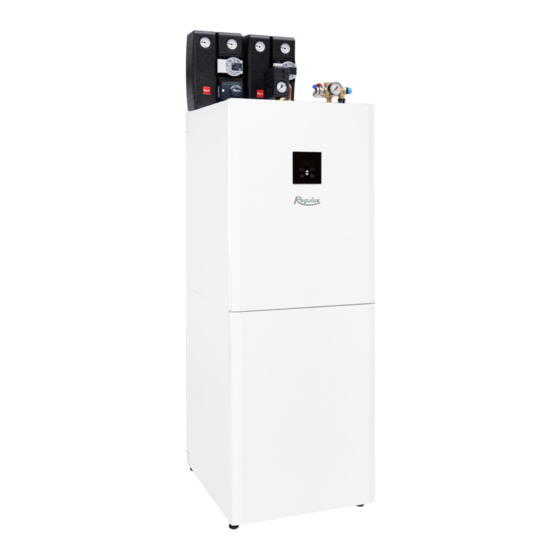
- Page 1 Installation and Operation Manual RegulusHBOX 212 RTC 3/1 RegulusHBOX...
-
Page 2: Table Of Contents
CONTENTS A. GENERAL INFORMATION ......................5 A1. Safety Instructions ......................5 A2. Application, Description ....................5 A3. Components ........................7 A4. Internal Hydraulic Connection ..................8 A5. Parameters ........................9 B. INSTALLATION, CONNECTION ....................11 B1. Dimensions ........................11 B2. Installation Site Requirements ..................12 B3. - Page 3 E6.4. Weather Compensating Heating Curve Settings ..........33 E7. AKU Zone ........................35 E8. Pool Heating ........................35 E9. Holidays ......................... 35 E10. DHW Menu (HOT WATER) ..................36 E10.1. Hot Water Heating by Heat Pump ..............36 E10.2. Hot Water Heating by Auxiliary Source ............36 E11.
- Page 4 F3.8. Settings of DHW Heating by the Heat Pump (DHW-HP) ........49 F3.9. Settings of DHW Heating by Auxiliary Source (DHW-E) ........49 F3.10. Settings of Thermal Store Heating ..............49 F3.11. Settings of DHW Recirculation ............... 49 F3.12. Statistics ......................49 F3.13.
-
Page 5: General Information
This Installation and Operation Manual forms an integral part of the product. Before starting any work, read this manual and keep it accessible at all times. Should you lose the manual, you can download the current version in pdf format from the website www.regulus.eu. A1. Safety Instructions ●... - Page 6 This controller is equipped with its own website (web server) permitting remote control through a web browser or from a smartphone or tablet with the application Regulus IR client installed (versions for Android and iOS are available).
-
Page 7: A3. Components
A3. Components 1 – Pump station of the heat pump circuit - included in supply 2 – Heating system safety group (3bar safety valve, air vent valve, pressure gauge, T-piece with a drain valve designed for heating system topping up) - included in supply 3 –... -
Page 8: A4. Internal Hydraulic Connection
A4. Internal Hydraulic Connection Included in HBOX supply Optional accessories │... -
Page 9: A5. Parameters
A5. Parameters Technical Data Total tank volume 210 l Total fluid volume in tank 189 l Fluid volume above the separating metal sheet 140 l Fluid volume below the separating metal sheet 49 l Fluid volume in DHW heat exchanger 21 l DHW heat exchanger surface area Fluid working temperature... - Page 10 Pressure Drop Diagram - heating Pressure Drop Diagram - DHW Q [l/min] Q [l/h] _____ Tepelné čerpadlo indoor piping to connect HP _ _ _ _ Otopný systém indoor piping to connect central heating Wilo Para 25/8 iPWM1 pump performance curves [m H - PWM signal │...
-
Page 11: Installation, Connection
B. INSTALLATION, CONNECTION B1. Dimensions Tipping height 1790 mm (without pump stations and safety groups connected) Pos. Description Connection Height [mm] Cold water G 3/4" F 1755 Hot water G 3/4" M 1700 Incoming from heat pump G 1" M 1700 Return to heat pump G 1"... -
Page 12: B2. Installation Site Requirements
B2. Installation Site Requirements ● RegulusHBOX shall be installed indoors only. ● Ensure that no water can enter RegulusHBOX at the installation site. ● Do not install the device in areas with a bath or shower in zones 0, 1 and 2. ●... -
Page 13: B3. Installation
B3. Installation Transport RegulusHBOX to the installation site in a vertical position. It is not permitted to transport RegulusHBOX in a horizontal position. Install RegulusHBOX on a level floor with sufficient floor loading capacity - the weight of RegulusHBOX without heating water is 148 kg, with water it is 360 kg. - Page 14 2 - mount the safety group of the heating system with the T-piece and G 1/2“ valve on the connection 6 (G 1“ M), connect the waste from the safety valve to the drain tundish located in the cover of RegulusHBOX. The safety group involves a safety valve, air vent valve and pressure gauge.
-
Page 15: B4.1 Hydraulic Variant With One Heating Circuit
B4.1 Hydraulic Variant with one heating circuit │... -
Page 16: B4.2 Hydraulic Variant With Two Heating Circuits
B4.2 Hydraulic Variant with two heating circuits │... -
Page 17: B5. Electrical Wiring
B5. Electrical Wiring B5.1. Cable Entry For the electrical connection of the RegulusHBOX, it is necessary to remove the upper front cover and the wiring cover located below it. LIFT Before opening the wiring cover, unscrew the two screws Two passages under the lid of the RegulusHBOX are used to connect cables Note: The power supply cable is used not only to supply RegulusHBOX, but... -
Page 18: B5.2. Terminal Block
B5.2. Terminal Block CONTROL OF HP CIRCULATION PUMP - CONNECTED RIPPLE CONTROL OVLÁDÁNÍ OBĚHOVÉHO ČERPADLA TČ - PŘIPOJENO SIGNAL SIGNÁL HDO MAINS HLAVNÍ PŘÍVOD HP POWER SUPPLY NAPÁJENÍ TČ CONTROL OF OPTIONAL EXTERNAL PUMP OVLÁDÁNÍ EXTERNÍHO VOLITELNÉHO ČERPADLA CIB BUS SBĚRNICE CIB SUPPLY OF HP CIRCULATION PUMP - CONNECTED NAPÁJENÍ... -
Page 19: B5.3. Complete Inner Wiring Diagram
B5.3. Complete Inner Wiring Diagram HLAVNÍ PŘÍPOJNÁ SVORKOVNICE / MAIN TERMINAL signal AI OBĚH.ČERP.TC / CIRC.PUMP.HP signal DI GND AI/DI (SOUČÁST ČERP. SKUP. V PŘÍBALU / +24VDC (PART OF ENCLOSED PUMP GROUPE -24VDC IN ACCESSORIES) IRL-8 ZÓN. VENT. TV / ZONE VAL. -
Page 20: B5.4. Wiring Diagram Of M&R Peripherals To Regulushbox
B5.4. Wiring Diagram of M&R Peripherals to RegulusHBOX UTP CAT5E RIPPLE CONTROL VSTUP SIGNÁLU HDO SIGNAL INPUT HDO N POWER SUPPLY INPUT VSTUP NAPÁJENÍ HBOX FOR HBOX POWER SUPPLY L3 TC VÝSTUP NAPÁJENÍ TC OUTPUT FOR HP L2 IR POWER SUPPLY OF A/DI11 NAPÁJENÍ... -
Page 21: B5.5. Connection And Adjustment Of Optional Accessories - Room Sensor/Unit, Thermostat
B5.5. Connection and Adjustment of Optional Accessories - room sensor/unit, thermostat In each heating zone, it is possible to measure the room temperature using one of the following elements: - Pt1000 room sensor - RC25 room unit - RCA room unit (buil-in display that is included in supply) - WiFi RSW 30 Wireless room sensor - current room thermostat with NO or NC contacts Assign the type of room sensor (unit) installed to the appropriate zone in the service menu of the... -
Page 22: B6. Pre-Commissioning Inspection
B6. Pre-commissioning Inspection Before commissioning the device, make sure that: • the heating system has been properly flushed and filled with clean and treated water • the installation site requirements specified in chapter B.2 of this manual have been respected •... -
Page 23: Settings Using The Main Display
C. SETTINGS USING THE MAIN DISPLAY A control panel designed for user system settings is located on the front cover. The panel consists of a display and six control buttons: ESC to return to the previous screen. ENTER to select and save a value Up and down arrows to scroll through menus or adjust values. -
Page 24: C1.1. Settings For Heating
C1.1. Settings for HEATING To access the HEATING menu from the home screen, press the SETTINGS button C1.2. Settings for HOT WATER You can access the HOT WATER menu from the home screen by pressing the SETTINGS button and then pressing the down arrow button once. │... -
Page 25: C1.3. Settings For Dhw Recirculation
C1.4. Other settings To access the menus for HEAT PUMP, ADDITIONAL SOURCE and REGULUS ROUTE from the home screen, press the SETUP button and then press the down arrow button three, four and five times. -
Page 26: How To Set Access To Controller Website
D. HOW TO SET ACCESS TO CONTROLLER WEBSITE The controller contains an integrated website showing an overview of the heating system and user settings. To reach web access to the controller‘s website it is necessary to connect the controller either to the local network or directly to the PC using a network cable. Alternatively, it is possible to use the IR Client mobile application. - Page 27 1. Click on Ethernet - a window with the connection status will open 2. Click on Properties at the bottom, the Ethernet properties window will open 3. Double-click on IP Protocol version 4 - a window with protocol properties will open. This window can also be accessed in other ways.
-
Page 28: D3. How To Connect Via Ir Client Mobile Application
Regulus IR Client is free to download from (for Android) and (for iOS). After logging in to the IR controller via the web interface using the Regulus IR Client application or the RegulusRoute service, the basic screen with tiles is displayed. │... -
Page 29: Setting The Controller Through Web Browser
When editing values (numbers, texts), it is necessary to confirm the change after each change by pressing the SAVE CHANGES button. Home page shown in the Regulus IR Client mobile application The drop-down menu to enter the individual sections for settings can be opened by clicking on the icon in the upper left corner;... -
Page 30: E2. Tiles For Heating And Hot Water
E2. Tiles for Heating and Hot Water When adjusting the temperature using the plus and minus buttons, the desired temperature is adj- usted depending on the current mode (T comfort, T setback). You will get to detailed zone The ON / OFF button is setting by clicking on this used to turn the zone on button. -
Page 31: E4. Display Of The Diagram (Diagram)
E4. Display of the Diagram (DIAGRAM) Schematic representation of your hydraulic connection with a clear display of important quantities, states and information. The diagram should therefore always correspond to your current hydraulic connection. For proper display in the mobile application, it is necessary to rotate the device for land- scape view. -
Page 32: E6. Heating Zone Settings (Zone 1 To 6)
E6. Heating Zone Settings (Zone 1 to 6) The heating zone can be switched on or off by the user with the ON/OFF button. If the zone is swit- ched off by the user, the circulation pump is switched off and the mixing valve is moved to the closed position. -
Page 33: E6.3. Summer/Winter Fuction Settings
E6.3. Setting the Winter/Summer function (blocking heating in the summer) When activating HEATING BLOCKED IN SET PERIOD, enter the date of beginning and end of the period when heating will be always blocked, disregarded of the current outdoor temperature. When activating HEATING BLOCKED BY OUTDOOR TEMPER., enter the time intervals for the set outdoor temperatures after which heating will be blocked (SUMMER mode permitted) and permitted (WINTER mode permitted). - Page 34 Object overheating at temperatures above zero If the building overheats at an outdoor temperature above zero, the heating water temperature must be reduced with the minus button. It can be seen from the graph that the heating water temperature is adjusted mainly at temperatures above the freezing point.
-
Page 35: E7. Aku Zone
Expert settings are intended for more experienced users, there are two pairs of plus and minus bu- ttons. One for temperatures above zero and the other for temperatures below the freezing point. By clicking on the individual buttons, the heating curve is reset mainly in the values corresponding to the location of the buttons according to the graphs above. -
Page 36: E10. Dhw Menu (Hot Water)
E10. DHW Menu (HOT WATER) DHW heating is divided into DHW-HP (DHW heating by heat pump), DHW-E (DHW heating by auxiliary source). If the hot water recirculation function is switched on, there is also a SET CIRCULATION tile. E10.1. Hot Water Heating by Heat Pump Hot water heating by heat pump can be switched on or off using the ON/OFF button. -
Page 37: E11. Hot Water Recirculation Settings
E11. Hot Water Recirculation Settings The DHW recirculation by auxiliary source can be switched on or off by the user with the ON/OFF button. Setting intervals Recirculation time - setting the running time of the circulation pump (pump running) Delay time - setting the delay time of the circulation pump (pump stopped) The time program settings are identical to the time program settings in zones 1 - 6. -
Page 38: E12.2. Solar Heating
E12.2. Solar Heating The solar circuit can be switched on or off by the user with the ON/OFF button (the safety recooling functions remain in operation when switched off). During commissioning, the service technician sets the right differential values for switching the solar system on and off. -
Page 39: E12.4. Regulushbox Electric Heating Elements
Information about faults or abnormal operation is sent automatically to the Regulus service department. If you want to send the information to other addresses as well, you can fill it in the E-mail Recipient line. Separate the addresses with a semicolon. -
Page 40: E13.6. Fault History
E13.5. Function Overview All functions of the controller are displayed in the Function Overview. Depending on the selected controller setting, the service- and user-switched functions are highligh- ted here. E13.6. Fault history Display of the heat pump fault history and history of other system faults (sensors, communications, modules ...). -
Page 41: E13.8. Universal Outputs
E13.8. Universal Outputs Information on universal functions (UNI function and UNI function 2). These functions are fully adj- ustable from the service interface. On the user level the information can be displayed on temperatu- res and function outputs and the parameters of Thermostat 1 (thermostat related to temperature 1) and Thermostat 2 (thermostat related to temperature 2) and Timers can be set. -
Page 42: Adjusting The Controller Through The Service Display
F. ADJUSTING THE CONTROLLER THROUGH THE SERVICE DISPLAY Warning: The service display is located in the electrical installation section of the device, where the live components are located. Therefore, the service display can only be operated by a service technician with electrical qualification. F1. -
Page 43: F2.2. Zone Display (Zone 1, Zone 2)
F2.2. Zone Display (zone 1, zone 2) 1 - zone status (information on the current status of the heating zone) 2 - actual and desired room temperature (if a room sensor is not used, the value is 0.0) 3 - correction of the desired room temperature; when a room unit is used, the „PJ“ symbol is displayed and the correction by this unit is displayed 4 - actual and desired heating water temperature to the zone The table below lists the possible operating states indicated on the service display and... -
Page 44: F2.3. Solar Thermal System Display
F2.3. Solar Thermal System Display 1 - solar collector temperature 2 - turn on the system 3 - ON = solar pump running 4 - mark of the currently heated hot water storage tank 5 – HW storage tank 1, actual temperature (desired in solar heating) 6 –... -
Page 45: F2.6. Display Of Heat Pump, Heat Pump Cascade (Hp In Series)
F2.6. Display of Heat Pump, Heat Pump Cascade (HP in series) 1 - status of heat pump No. 1, No. 2 and No. 3. This section shows the states of the heat pumps that are enabled on the service level. The states can be as follows: OFF - service : heat pump is turned off by a heating engineer... -
Page 46: F2.7. Display With Firmware Version And Release Date
F2.7. Display with Firmware Version and Release Date F2.8. Controller in Factory Settings If there is the screen shown on the display (see below) with a warning about setting the controller to factory settings, it is necessary that a service technician sets the relevant parameters of the controller. F2.9. -
Page 47: F3. User Settings
F3. User Settings Use the ◄ ► buttons to select between the options in the user settings; confirm the selection with the button; after completing all settings, press the × button to return to the first - basic display. F3.1. Heating Zones Basic settings of the heating zone T comfort (°C) setting the comfort temperature in the zone (desired room temperature) -
Page 48: F3.3. Time Programs
F3.3. Time Programs Setting the time program by days - set for each day of the week two transitions from setback mode to comfort mode and two transitions from comfort mode to setback mode. Setting the time program block by block - set the transitions similarly for the Mon-Fri and Sat-Sun block. -
Page 49: F3.8. Settings Of Dhw Heating By The Heat Pump (Dhw-Hp)
F3.8. Settings of DHW Heating by the Heat Pump (DHW-HP) DHW on user activation of DHW heating by the heat pump T comfort (°C) desired temperature in „comfort“ mode T setback (°C) desired temperature in „setback“ mode During the day, the controller switches the desired DHW temperature from the heat pump according to the set time program. F3.9. -
Page 50: F3.13. Operating Data
F3.16. RegulusRoute - Service Connection Parameters RegulusRoute service allows remote access to the controller without the need to use a public IP address. Pleaase contact Regulus to configure the service. RegulusRoute (yes/no) indicates whether the service is switched on Status... -
Page 51: F4. Add-On Modules
F4. Add-on Modules When selecting Add-on Modules in the main menu, user information for add-on modules can be viewed if they are used in the controller. F4.1. Fireplace Module Temperature (°C) – displays the fireplace flow temperature. Damper (%) – displays how opened the fireplace air inlet damper is. DHW pump –... -
Page 52: Maintenance
G. MAINTENANCE G1. Maintenance by the User It is recommended to perform this type of maintenance once a month: • Pressure check (locally or remotely via remote access). If necessary, air vent and top up water to the heating system. •... -
Page 53: G3. Removing The Wiring Cover
G3. Removing the Wiring Cover Warning: Danger of electric shock if live parts are touched! Before starting work, disconnect the RegulusHBOX from the power supply (by switching off the relevant circuit breaker in the house switchboard). Disassembly of the wiring cover may only be carried out by a person professionally qualified in ac- cordance with EN 50110-1! The cover is attached with two screws at the bottom. -
Page 54: G5. Discontinuing Operation
G.5. Discontinuing Operation If there is a risk of water freezing in the device (e.g. if the device is out of operation in an unheated room), drain all water from the RegulusHBOX, the heat pump and the pipes - especially in places where the temperature may drop below 0 °C. -
Page 55: H2. Record Of Repairs And Inspections
H.2. Record of Repairs and Inspections Custo- Service company Date Operation performed mer‘s Name, signature and stamp signature │... - Page 56 ©2023 We reserve the right to errors, changes and improvements without prior notice. REGULUS spol. s r.o. E-mail: sales@regulus.eu Web: www.regulus.eu...
Need help?
Do you have a question about the RegulusHBOX 212 RTC 3/1 and is the answer not in the manual?
Questions and answers