User Manuals: Carel heaterSteam UR006 Humidifier
Manuals and User Guides for Carel heaterSteam UR006 Humidifier. We have 2 Carel heaterSteam UR006 Humidifier manuals available for free PDF download: User Manual
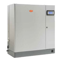
Carel heaterSteam UR006 User Manual (72 pages)
Electric resistance humidifier
Brand: Carel
|
Category: Humidifier
|
Size: 5 MB
Table of Contents
Advertisement
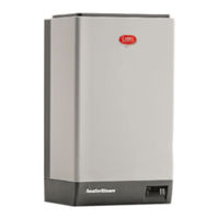
Carel heaterSteam UR006 User Manual (72 pages)
electrical heater humidifier
Brand: Carel
|
Category: Humidifier
|
Size: 2 MB