Advertisement
INSTALLATION AND GAUGING PROCEDURE
For copper cables and 8 GA to 250 MCM and
01
1. Strip cable without cutting or nicking the strands.
2. Select the side of the tool according to the type of
connector and cable combination to be installed.
3. Move indenter by turning the adjusting wheel until
the pointer slot aligns with the selected cable size
line. The wheel should be in a positive detented
position (See figure 1).
Connector
Cable Size
COPPER CABLES
Line
Figure 1
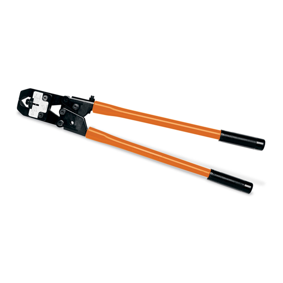
ADJUSTABLE CRIMPER
for aluminum cables 8 GA to 3/0
Catalog Number TBM4S
WARNING
HANDLES ARE NON-INSULATING.
DO NOT CRIMP ON ENERGIZED WIRES.
INSTALLING PROCEDURE
Nest
Indenter
Adjusting
Wheel
Pointer Slot
Type of Cable
4. Insert cable into connector barrel until it bottoms.
5. Locate connector in the tool between the die nest
and indenter (See Figure 2).
6. Crimp connector by closing the handles. Apply
as many crimps as required. Refer to instructions
packed with connectors for required number of
crimps.
Cable
WARNING
TBM4S is equipped with th SHURE-STAKE
Compelling Mechanism. Keep fingers and other body
parts clear of die nest during operation of this tool.
Figure 2
Die Nest
Connector
Die Indentor
Full Stroke
®
TA01454 B page 1 of 2
Advertisement
Table of Contents

Subscribe to Our Youtube Channel
Related Manuals for Thomas & Betts TBM4S


Summary of Contents for Thomas & Betts TBM4S
- Page 1 Die Indentor Cable Size COPPER CABLES Line WARNING Type of Cable TBM4S is equipped with th SHURE-STAKE Full Stroke ® Compelling Mechanism. Keep fingers and other body parts clear of die nest during operation of this tool. Figure 1 Figure 2...
- Page 2 HANDLE ADJUSTMENT PROCEDURE CHECKING HANDLE ADJUSTMENT HANDLE ADJUSTMENT PROCEDURE 1. Lay the tool on a flat surface as shown in Figure 3. 1. Turn Adjustment screw clockwise to increase Open handle and release it so that it will close of its handle spread and counterclockwise to decrease own weight.
Need help?
Do you have a question about the TBM4S and is the answer not in the manual?
Questions and answers