Advertisement
Quick Links
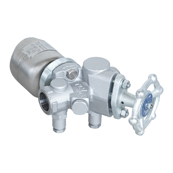
TRAP STATION
Important
This product connects to TLV QuickTrap series trap units. For the
connection procedure and the installation procedure, see the instruction
manual included with the trap unit, and make sure to work safely.
Safety Considerations
•
Read this section carefully before use and be sure to follow the instructions.
•
Installation, inspection, maintenance, repairs, disassembly, adjustment and valve opening/closing should be carried out only
by trained maintenance personnel.
•
The precautions listed in this manual are designed to ensure safety and prevent equipment damage and personal injury.
For situations that may occur as a result of erroneous handling, three different types of cautionary items are used to indicate
the degree of urgency and the scale of potential damage and danger: DANGER, WARNING and CAUTION.
•
The three types of cautionary items above are very important for safety: be sure to observe all of them as they relate to
installation, use, maintenance, and repair. Furthermore, TLV accepts no responsibility for any accidents or damage
occurring as a result of failure to observe these precautions.
Symbol
CAUTION
: Indicates that there is a possibility of injury or equipment/product damage
Install properly and DO NOT use this product outside the recommended operating pressure,
temperature and other specification ranges.
Improper use may result in such hazards as damage to the product or malfunctions that may lead to
serious accidents. Local regulations may restrict the use of this product to below the conditions quoted.
Take measures to prevent people from coming into direct contact with product outlets.
Failure to do so may result in burns or other injury from the discharge of fluids.
When disassembling or removing the product, wait until the internal pressure equals
atmospheric pressure and the surface of the product has cooled to room temperature.
Disassembling or removing the product when it is hot or under pressure may lead to discharge of
fluids, causing burns, other injuries or damage.
Do not use excessive force when connecting threaded pipes to the product.
Over-tightening may cause breakage leading to fluid discharge, which may cause burns or other injury.
Do not stand on or apply body weight to the handwheel.
The handwheel may break, resulting in injury or other accidents.
Do not carry the product by its handwheel.
The handwheel may turn causing the balance to shift and the product to be dropped, resulting in injury
or other accidents.
CAUTION
Always wear eye protection and heat-resistant gloves when operating the blowdown/test valve.
Failure to do so may result in burns or other injury.
When operating the blowdown/test valve, stand to the side well clear of the outlet to avoid contact with
internal fluids that will be discharged. Operate the valve slowly and surely, taking care to avoid the area
from which internal fluids are discharged and any fluids deflected off piping or the ground etc.
Failure to do so may result in burns or other injury.
Do not tighten the BD2 valve or the BD2 valve seat in excess of the appropriate tightening torque.
Over-tightening may cause breakage to threaded portions, which may cause burns, other injuries or damage.
Do not excessively loosen the BD2 valve when opening the blowdown/test valve.
The valve stopper pin installed to prevent the BD2 valve from being removed may break and internal
pressure may result in the BD2 valve being blown off, leading to injuries, damage and fluid discharge,
causing burns.
Use only under conditions in which no freeze-up will occur.
Freezing may damage the product, leading to fluid discharge, which may cause burns or other injury.
Use only under conditions in which no water hammer will occur.
The impact of water hammer may damage the product, leading to fluid discharge, which may cause
burns or other injury.
Installation & Operational Consideration
Before installing the product, blow out the piping to remove any piping scraps, dirt, oil and scale.
Failure to do so may lead to early clogging due to an initial heavy load of foreign material in the piping.
Do not remove the product from its box or protective covering until just prior to installation.
CAUTION
Remove any plugs or seals just prior to installation.
The protective covers keep damage causing foreign material out of the product.
Do not use a wire-brush or other hard devices to clean the screen.
Doing so may damage or detach the meshed screen.
V1P/V2P Series
Specifications
V1P-RL / V1P-RB / V1P-RW / V1P-RV /
Model
V1P-LB / V1P-LW / V1P-LV
Name
Inlet/Outlet Valve
Only at the inlet side
Body Material
Size
Max. Allowable Press. PMA* /
Max. Allowable Temp. TMA*
Max. Operating Press. PMO** /
Max. Operating Temp. TMO**
Applicable Fluid
Free Float Steam Trap
S3, S5, S5H, S3-K, S5-K
Connectable TLV products
(Trap Unit Models)
NOTE: Some models may not be
available in all regions.
Other trap units may be applicable. Contact TLV for QuickTrap models not listed.
* Maximum Allowable Pressure (PMA) and Maximum Allowable Temperature (TMA) are PRESSURE
SHELL DESIGN CONDITIONS for trap station only, NOT OPERATING CONDITIONS.
** For trap station only; further restricted by mounted trap unit.
Model
V1P-RL
or
Appearance
Flow Diagram
or
Flow Direction
Right or Left
Blowdown Valve
̶
̶
Test Valve
Model
V1P-RW
Appearance
Flow Diagram
Right
Flow Direction
Blowdown Valve
●
●
Test Valve
Model
V2P-RL
or
Appearance
Flow Diagram
or
Right or Left
Flow Direction
Blowdown Valve
̶
̶
Test Valve
Manufacturer:
881 Nagasuna, Noguchi, Kakogawa, Hyogo 675-8511, JAPAN
Tel: [81]-(0)79 - 422 - 1122
Copyright
2017 by TLV CO., LTD. All rights reserved.
○
C
V2P-RL / V2P-RB / V2P-LB
TRAP STATION
Inlet/outlet side
ASTM A105 or ASTM A182 F304
/
/
15, 20 mm (
1
,
3
in)
2
4
5.0 MPaG (710 psig) / 425 °C (800 °F)
5.0 MPaG (710 psig) / 425 °C (800 °F)
Steam, Condensate
Disc Type Steam Trap
Thermostatic Steam Trap
P46UC
L5, L21, L32, L5-C, L21-C, L32-C
P32
(1 MPa = 10.197 kg/cm
V1P-RB
Right
●
̶
V1P-LW
V1P-RV
Left
Right
●
̶
●
●
V2P-RB
Right
●
●
Fax: [81]-(0)79 - 422 - 0112
X1
)
2
V1P-LB
Left
●
̶
V1P-LV
Left
̶
●
V2P-LB
Left
●
●
Advertisement

Subscribe to Our Youtube Channel
Related Manuals for TLV V1P Series


Summary of Contents for TLV V1P Series
- Page 1 The three types of cautionary items above are very important for safety: be sure to observe all of them as they relate to Connectable TLV products installation, use, maintenance, and repair. Furthermore, TLV accepts no responsibility for any accidents or damage (Trap Unit Models) occurring as a result of failure to observe these precautions.
- Page 2 The test valve is installed at the outlet of the trap. By closing the outlet valve for the trap station and opening the test valve it becomes possible to test the operation of the trap. The TLV blowdown valve BD2 is used for both...
Need help?
Do you have a question about the V1P Series and is the answer not in the manual?
Questions and answers