Sign In
Upload
Download
Table of Contents
Contents
Add to my manuals
Delete from my manuals
Share
URL of this page:
HTML Link:
Bookmark this page
Add
Manual will be automatically added to "My Manuals"
Print this page
×
Bookmark added
×
Added to my manuals
Manuals
Brands
Dru Manuals
Indoor Fireplace
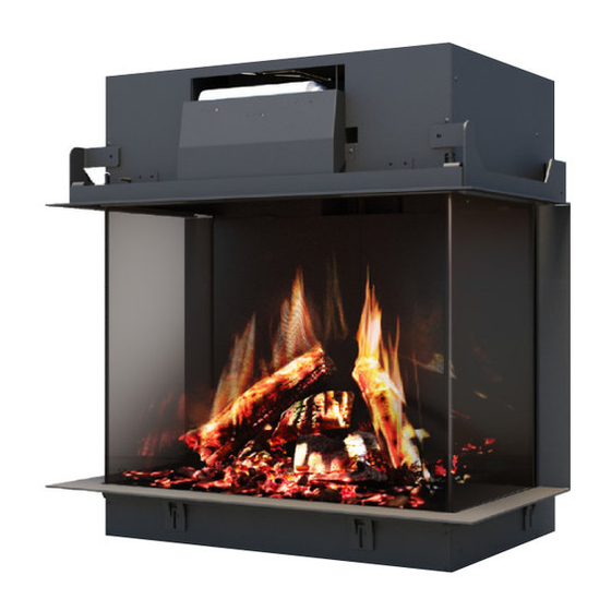
Virtuo 75
Installation and user manual
Dru Virtuo 75 Installation And User Manual
Hide thumbs
1
Table Of Contents
2
3
4
5
6
7
8
9
10
11
12
13
14
15
16
17
18
19
20
21
22
23
24
25
26
27
28
29
30
31
32
33
34
35
36
37
38
39
40
page
of
40
Go
/
40
Contents
Table of Contents
Bookmarks
Table of Contents
Table of Contents
Introduction
CE Declaration
User Manual
General
Precautions and Safety Instructions
Taking the Appliance in Operation
For the First Time
Protection
Projector Safety Mode
Remote Control
Replacing/Placing Batteries
Operation Via the DRU Virtuo App
Main Switch
Maintenance
Cleaning the Glass Pane
Environment
General
The Appliance
Warranty
Installation Manual
Step-By-Step Installation Plan
Safety
Regulations
Safety Instructions
Preparation
Unpacking
Electric Connection
Switch Contact Connection
Installation
Placing the Appliance
Placing Appliance
Additional Installation Options
Platform Combined with Lower Decorative Strip
Platform Adjacent to the Glass
Back and Side Wall Adjacent to the Glass of the Side Pane
Placing the Chimney Breast
The Appliance
Glass Panes
Removing the Front Glass Pane
Placing the Glass Pane
Cleaning the Glass Pane
Preparing the Projector for First Use
Wood Set, Chips and Glow Rock Set
Installing the Wood Set
Final Check
Delivery
Projector & Projector Mirror
Heating Element
Parts
Maintenance
Malfunctions
Advertisement
Quick Links
1
Remote Control
Download this manual
I n s ta l l a ti on a n d us e r m a n ua l
Virtuo 75, Virtuo 80/2 and Virtuo 80/3
English
Store this document in a safe place
959.124.01.UK
Table of
Contents
Previous
Page
Next
Page
1
2
3
4
5
Advertisement
Table of Contents
Need help?
Do you have a question about the Virtuo 75 and is the answer not in the manual?
Ask a question
Questions and answers
Related Manuals for Dru Virtuo 75
Indoor Fireplace Dru Venteo E Installation And Service Manual
Electrical decorative fireplace (52 pages)
Indoor Fireplace Dru VENTEO E User Manual
Electrical decorative fireplace (44 pages)
Indoor Fireplace Dru Virtuo Evolve 100 Installation Manual
(60 pages)
Indoor Fireplace Dru Virtuo 100 Evolve User Manual
(32 pages)
Indoor Fireplace Dru Virtuo Evolve 150 Installation Manual
(52 pages)
Indoor Fireplace Dru Virtuo 80/3 Installation And User Manual
(40 pages)
Indoor Fireplace Dru Virtuo Evolve 130/3 Installation Manual
(60 pages)
Indoor Fireplace Dru Virtuo Evolve 180 Installation Manual
(60 pages)
Indoor Fireplace Dru Romano Installation And Operation Instructions Manual
Dru romano natural gas fire instructions for installation and operations (19 pages)
Indoor Fireplace Dru Apollo 100 Instructions For Installation Manual
Version with a set of logs (60 pages)
Indoor Fireplace Dru G25 Installation Manual
Milo (40 pages)
Indoor Fireplace Dru Metro 130 Tunnel Instructions For Installation Manual
Decorative gas heating appliance (28 pages)
Indoor Fireplace Dru Metro 130 XT Tunnel Installation Manual
(36 pages)
Indoor Fireplace Dru Trio G20 Instructions For Installation Manual
Freestanding atmospheric gas heating appliance (20 pages)
Indoor Fireplace Dru Metro 100 XT Tunnel Instructions For Installation Manual
(28 pages)
Indoor Fireplace Dru Spirit Instructions For Installation And Operation Manual
(20 pages)
This manual is also suitable for:
Virtuo 80/2
Virtuo 80/3
Table of Contents
Print
Rename the bookmark
Delete bookmark?
Delete from my manuals?
Login
Sign In
OR
Sign in with Facebook
Sign in with Google
Upload manual
Upload from disk
Upload from URL


Need help?
Do you have a question about the Virtuo 75 and is the answer not in the manual?
Questions and answers