
Subscribe to Our Youtube Channel
Related Manuals for Extron electronics PowerCage FOX Tx HDMI


Summary of Contents for Extron electronics PowerCage FOX Tx HDMI
- Page 1 User Guide Fiber Optic Extenders PowerCage FOX Tx/Rx HDMI Streaming HDMI Encoder 68-1994-01 Rev. B 11 20...
- Page 2 Safety Instructions Safety Instructions • English Istruzioni di sicurezza • Italiano AVVERTENZA: Il simbolo, , se usato sul prodotto, serve ad This symbol, , when used on the product, is intended to WARNING avvertire l’utente della presenza di tensione non isolata pericolosa alert the user of the presence of uninsulated dangerous voltage within the all’interno del contenitore del prodotto che può...
- Page 3 安全記事 • 繁體中文 안전 지침 • 한국어 警 告 경고: 이 기호 가 제품에 사용될 경우, 제품의 인클로저 내에 있는 若產品上使 用此 符 號 , 是 為了提 醒 使 用者,產品 機 殼內存 在 著 접지되지 않은 위험한 전류로 인해 사용자가 감전될 위험이 있음을 可能會導致觸電之風險的未絕緣危險電壓。...
- Page 4 FCC Class A Notice This equipment has been tested and found to comply with the limits for a Class A digital device, pursuant to part 15 of the FCC rules. The Class A limits provide reasonable protection against harmful interference when the equipment is operated in a commercial environment.
- Page 5 Selectable items, such as menu names, menu options, buttons, tabs, and field names are written in the font shown here: From the menu, select File Click the button. Specifications Availability Product specifications are available on the Extron website, www.extron.com. Extron Glossary of Terms http://www.extron.com/technology/ A glossary of terms is available at glossary.aspx...
-
Page 7: Table Of Contents
Contents Introduction Remote Control ............ 1 ..........17 About this Guide ........... 1 Serial Ports ............17 About the PowerCage FOX HDMI Transmitters Simple Instruction Set Control ......18 and Receivers ............1 Host-to-unit Instructions ......... 18 Transmitter............2 Unit-initiated Messages........18 Receiver ............ - Page 8 PowerCage FOX HDMI • Contents viii...
-
Page 9: Introduction
Features • About this Guide This guide contains information about the Extron PowerCage FOX Tx HDMI transmitter ® and PowerCage FOX Rx HDMI receiver. These units are modular board-designed fiber optic transmitters and receivers for the PowerCage Modular Power Enclosures. -
Page 10: Transmitter
Typical PowerCage FOX Tx/Rx HDMI Application Transmitter The PowerCage FOX Tx HDMI transmitter accepts HDMI video or DVI-D video (with an applicable adapter), at resolutions up to 1920 x 1200 at 60 Hz. The video input can also include embedded audio. -
Page 11: Receiver
System Compatibility The PowerCage FOX Tx HDMI transmitter operates in either of two modes, selected under RS-232 control, for compatibility with other, non-HDMI, units: Plus — Supports resolutions up to 1920 x 1200 @ 60Hz. The fiber optic output of the •... -
Page 12: Cable Transmission Modes
Video input — The transmitter accepts a single link of HDMI or DVI-D video. EDID emulation mode (Display Data Channel [DDC]) — The PowerCage FOX Tx HDMI transmitter provides a selector switch for specifying the rate of the incoming digital video signal. - Page 13 Upgradable firmware — The firmware that controls the operation of each unit can be upgraded in the field via the Configuration port on the PowerCage enclosure without taking the unit out of service. Firmware upgrades are available for download on the Extron website, www.extron.com, and they can be installed using the FOX Extenders Control Program.
-
Page 14: Installation And Basic Operation
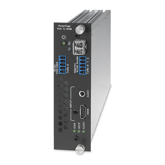
Installation and Basic Operation This section describes the installation and operation of the PowerCage FOX HDMI, including: • Mounting the Units • Rear Panel Connections, Controls, and Indications Transmitter Side Panel Controls • • PowerCage Front Panel Port, Control, and Indicators Operation •... - Page 15 RS-232 Over Fiber port — If you want the transmitter and receiver RS-232 OVER FIBER system to pass serial command signals between the transmitter and receiver, for example for serial control of a projector, connect the host device Tx Rx to the transmitter and the secondary device to the receiver via the leftmost three poles on the left (Tx, Rx, and _) of the 5-pole captive screw connectors on both units (see...
- Page 16 WARNING: These units output continuous invisible light, which may be harmful to the eyes; use with caution. For additional safety, plug the attached dust caps into the optical transceivers when the fiber cable is unplugged. AVERTISSEMENT : Ces unités DMS émettent une lumière invisible continue, qui peut être dangereuse pour les yeux ;...
- Page 17 Receiver fiber optic connectors and LEDs — WARNING: These units output continuous invisible light, which may be harmful to the eyes; use with caution. For additional safety, plug the attached dust caps into the optical transceivers when the fiber cable is unplugged. AVERTISSEMENT : Ces unités DMS émettent une lumière invisible continue, qui peut être dangereuse pour les yeux ;...
- Page 18 Connect the free end of this fiber optic cable to either: • The Rx connector on the PowerCage FOX Tx transmitter (item on page 9) ã or to any other compatible Extron fiber optic device • The Rx connector on another receiver in the daisy chain. Tx and Rx LEDs —...
-
Page 19: Making Connections
Making Connections HDMI connectors HDMI signals run at a very high frequency and are especially prone to errors caused by bad video connections, too many adapters, or excessive cable length. To avoid the loss of an image or jitter, follow these guidelines: Do not exceed 16.4 feet (5 meters) on the input of the PowerCage FOX HDMI •... - Page 20 RS-232 connectors The RS-232 Over Fiber port (see figure 7) is for transmission of serial signals, such as projector control signals, between the transmitter and receiver. The Remote RS-232 port is for remote control of the transmitter and receiver. The protocol for the Remote RS-232 port is as follows: •...
-
Page 21: Transmitter Side Panel Controls
Audio output connector See figure 9 to properly wire a captive screw output connector. The connector is included with transmitter, but you must supply the audio cable. Use the supplied tie-wrap to strap the audio cable to the extended tail of the connector. NO GROUND HERE Ring Sleeves... -
Page 22: Powercage Front Panel Port, Control, And Indicators
PowerCage Front Panel Port, Control, and Indicators The following features are on the front panel of the PowerCage enclosure (see figure 11). COMM COMM SELECT TEMP POWER CONFIG ALARM PowerCage 1600 Figure 11. PowerCage Front Panel Features Comm LED (16 board locations) — This LED lights to indicate that the board at this location is selected for connection to the Configuration port (item ). - Page 23 Configuration port — This 2.5 mm mini stereo jack serves the same serial communications function as the Remote RS-232 port on the transmitter or receiver board, but is easier to access than the ports on the boards after the units have been installed and cabled. The , included with the PowerCage enclosure, 9-pin D to 2.5 mm mini jack TRS RS-232 cable but also available separately, part number 70-335-01 (see figure 13), can be used for this...
-
Page 24: Operation
Operation After the transmitter, all receivers, and their connected devices are powered up, the system is fully operational. If any problems are encountered, verify that the cables are routed and connected properly, and that all display devices have identical resolutions and refresh rates. If your problems persist, call the Extron S3 Sales &... -
Page 25: Remote Control
Remote Control This section describes the remote control operation of the PowerCage FOX HDMI, including: Serial Ports • • Simple Instruction Set Control • FOX Extenders Control Program Serial Ports The transmitter and receiver boards each have an RS-232 serial port on a 3 pins of a 5-pin captive screw connector that can be connected to a host device (see item on page 7). -
Page 26: Simple Instruction Set Control
When a local event, such as an equipment power-up, occurs, the unit responds by sending a message to the host. The unit-initiated messages are listed below: (c) Copyright 20nn, Extron Electronics PowerCage FOX Tx HDMI, Vn.nn, 70-889-nn ]] - or - (c) Copyright 20nn, Extron Electronics PowerCage FOX Rx HDMI, Vn.nn, 70-889-nn ]]... -
Page 27: Using The Command And Response Tables
Using the Command and Response Tables The command and response tables begin on page 20. Either uppercase or lower case letters are acceptable in the command field except where indicated for the audio level (gain and attenuation) commands. Symbols are used throughout the table to represent variables in the command and response fields. - Page 28 Command and Response Table for Transmitter SIS Command Command ASCII Command Response Additional Description (Host to Unit) (Unit to Host) Switch status Request EDID and refresh Stat EdidMdr •Vrate rate switch positions Example: EDID switch is set to 15 (1080p) and the vertical Stat EdidMdr15•Vrate2 rate switch is set to 2 (60 Hz).
- Page 29 Command ASCII Command Response Additional Description (Host to Unit) (Unit to Host) Audio input gain and attenuation NOTES • The set gain (G) and set attenuation (g) commands are case sensitive. The increment level, decrement level, and show level are not case sensitive.
- Page 30 Command ASCII Command Response Additional Description (Host to Unit) (Unit to Host) Information requests Information request 1Lnk •2Lnk •Vid •Aud • •Tx The unit responds with the current status (signal detected) of optical link 1, optical link 2, the video input, and the audio link; the fiber optic transmission mode (singlemode or multimode);...
- Page 31 Command ASCII Command Response Additional Description (Host to Unit) (Unit to Host) Symbol definitions for receiver SIS commands = Carriage return/line feed = Carriage return (no line feed) = Pipe (can be used interchangeably with the character) • = space = Escape key = Can be used interchangeably with the character...
- Page 32 Command ASCII Command Response Additional Description (Host to Unit) (Unit to Host) Auto memory Disable auto memory 55*0# Img0 Enable auto memory 55*1# Img1 Show auto memory status Audio mute Mute the audio Silence the audio output of the receiver. Amt1 Unmute the audio The receiver outputs audio.
- Page 33 Command ASCII Command Response Additional Description (Host to Unit) (Unit to Host) Video shutdown delay NOTES • The Set Video Delay command delays the digital video to help monitors sync correctly during an input rate change. • Only video is delayed. Embedded audio is not delayed. Set delay X2)] Delay video by an interval of...
-
Page 34: Fox Extenders Control Program
Click Download for the FOX Extenders software ( Follow the instructions that appear on the screen. By default, the installation creates a C:\Program Files\Extron\FOX_Extenders directory, and it places four icons into a group folder named “Extron Electronics\FOX Extender Control Program” The four installed icons are: •... -
Page 35: Starting The Program
Starting the Program Start the Extron FOX Extenders program as follows: Click > > > Start Programs Extron Electronics FOX Extenders > Control Program FOX Extenders The Communication Setup window appears (see figure 15). Figure 15. Communication Setup Window Select the Com port to which your transmitter or receiver is connected. Click . - Page 36 Status area Figure 17. Status Area The status area provides indications of the connection status. HDMI indicator — This indicator is green when the transmitter detects a sync signal • on its HDMI video input • Audio indicator — This indicator is green when the transmitter detects a low level audio signal for a short period.
- Page 37 Audio Adjustment area NOTE: The Audio Adjustment area controls are available only if your computer is connected to the transmitter. Audio Gain/Attenuation slider — Click and drag the Audio Gain/ Attenuation slider control to select the input audio gain or attenuation value, from -18 dB to +10 dB in 1.0 dB increments.
- Page 38 HDCP area NOTES: • The HDCP Authorized controls are available only if your computer is connected to the transmitter. • The HDCP Notification controls are available only if your computer is connected to the receiver. • Both sets of radio buttons cannot be available for selection at the same time.
- Page 39 Video Bit Depth area NOTE: The Video Bit Depth area radio buttons are available only if your computer is connected to the receiver. The Video Bit Depth radio buttons allow you to force the bit depth to 8 bits or to set it to auto.
-
Page 40: Firmware Upgrade
Firmware Upgrade Firmware can be upgraded for each unit via the PowerCage front panel Configuration port using the Extron Firmware Loader utility from the Windows-based control program. Downloading the firmware from the Web site To obtain the latest version of firmware for your PowerCage FOX unit: Visit the Extron website, www.extron.com, click the Download tab, and then click the Firmware link on the left sidebar menu (see figure 17). - Page 41 Loading the firmware to the transmitter and receiver To load a new version of firmware to your transmitter and receiver, call the Firmware Loader software from within the FOX Extenders Control Program. The serial port on your computer must be connected to the PowerCage front panel Configuration port and the unit to be updated must be selected (see item on page 7 and...
- Page 42 Click . The Firmware Loader window appears (see figure 21, 1 1 1 1 1 1 1 1 1 1 1 1 1 Figure 21. Extron Firmware Loader Window Select the PowerCage FOX unit and click > . The Choose Firmware File File Open screen appears (see figure 22).
- Page 43 In the Firmware Loader window, click Begin (see figure 23, The Total Progress and Progress status bars show the progress of the upload. The firmware upload to the unit may take several minutes. Once the status bars have progressed from 0% to 100%, and Status is listed as Completed, the firmware loader utility resets the unit.
-
Page 44: Powercage Board Installation
PowerCage Board Installation Up to 16 single slot or 8 dual slot input/output boards can be inserted into the PowerCage enclosure. The PowerCage transmitters and receivers are all dual slot boards. NOTE: The boards are hot-swappable, and can be installed or removed without disconnecting power to the PowerCage enclosure. - Page 45 Extron Warranty Extron warrants this product against defects in materials and workmanship for a period of three years from the date of purchase. In the event of malfunction during the warranty period attributable directly to faulty workmanship and/ or materials, Extron will, at its option, repair or replace said products or components, to whatever extent it shall deem necessary to restore said product to proper operating condition, provided that it is returned within the warranty period, with proof of purchase and description of malfunction to: USA, Canada, South America,...
Need help?
Do you have a question about the PowerCage FOX Tx HDMI and is the answer not in the manual?
Questions and answers