Sign In
Upload
Manuals
Brands
Aplisens Manuals
Accessories
PRE-28.Modbus
Aplisens PRE-28.Modbus Manuals
Manuals and User Guides for Aplisens PRE-28.Modbus. We have
3
Aplisens PRE-28.Modbus manuals available for free PDF download: User Manual
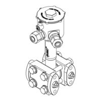
Aplisens PRE-28.Modbus User Manual (48 pages)
SMART PRESSURE AND DIFFERENTIAL PRESSURE TRANSMITTERS
Brand:
Aplisens
| Category:
Transmitter
| Size: 3 MB
Table of Contents
Table of Contents
5
1 Introduction
8
Purpose of the Document
8
2 Safety
8
3 Transport and Storage
8
Delivery Check
8
Transport
8
Storage
8
4 Guarantee
9
5 Identification
9
Manufacturer's Address
9
Transmitter Identification
9
CE Mark, Declaration of Conformity
9
Table 1. Symbols Occurring on the Transmitter Nameplate
9
6 Installation
10
General Recommendations
10
Installation Instructions for Transmitters with Distance Separators
10
7 Electrical Connection
11
Cable Connection to Transmitter Internal Terminals
11
Connection of Transmitters with PKD, PZ, SG, PM12 Type Connector (Cable Connection)
12
Power Supply
12
Resistance Load in Power Supply Line
12
Table 2. Connection, Output Signals
12
Table 3. Permissible Transmitter Supply Voltages
12
Transmitter Supply Voltage
12
Equipotential Bonding
13
Final Inspection of Cabling
13
Overvoltage Protection
13
Specifications of Electrical Switching Terminals
13
8 Operation
14
Description
14
Details of RS485 "Half-Duplex
14
Limited Digital Signal Incremental Rate
14
Fail Safe" Mode
15
1/16 of Bus Load
15
Line Transmission
15
Polarizing Resistors
15
Common Mode Voltage on RS485 Bus
15
Introduction
14
Physical Layer for RS485 Data Transfer
14
Data Link Layer
16
Modbus RTU Serial Transmission Mode
16
Modbus RTU Message Format
17
Modbus RTU Message Transfer Rules
17
Primary Rules
17
Error Handling
18
Application Layer, Description of Implemented Functions
19
Manufacturer/User Functions
19
0X64 (100) „Read Coefficients
19
0X65 (101) „Write Coefficients
21
0X66 (102) „Set Modbus Device Address (FLASH)
21
0X67 (103) „Set Speed, Parity, Stop
22
0X68 (104) „Perform Action
22
0X69 (105) „Set Modbus Device Address (RAM)
22
System Functions
19
0X03 (3) "Read Holding Register
19
0X2B (43) "Read Device Identification
19
Modbus Register Layout, Registers from 0X0000 or 0X0100 or 0X9C41 (40001 Dec) Address
23
Request Message with the Function 0X03 for 3 Different Addresses Fields, Reading All Registers
24
Request Message with the Function 0X03 for 3 Different Addresses Fields, Reading the IEEE754 Process Variable Stored in 2 Registers
24
Data from Registers Readable Using Function 03
25
Register 0X0000 or 0X0100 or 0X9C41, User Value, % Control of the Set Range
25
Register 0X0002 or 0X0104 or 0X9C43, Pressure of Sensor 1
26
Register 0X0004 or 0X0108 or 0X9C45, Pressure of Sensor 2
26
Register 0X0006 or 0X010C or 0X9C47, Temperature of Sensor 1
26
Register 0X0008 or 0X0110 or 0X9C49, CPU Temperature
26
Register 0X000A or 0X0114 or 0X9C4B, Temperature of Sensor 2
26
Register 0X000C or 0X0118 or 0X9C4D, Standby
26
Register 0X000E or 0X011C or 0X9C4F, Standby
26
Register 0X0010 or 0X0120 or 0X9C51, User Value
26
Register 0X0011 or 0X0122 or 0X9C52, Pressure of Sensor 1 - Binary Format, Integer and Sign
27
Register 0X0012 or 0X0124 or 0X9C53, Pressure of Sensor 2
27
Register 0X0013 or 0X0126 or 0X9C54, Temperature of Sensor 2 - Binary Format, Integer and Sign
27
Register 0X0014 or 0X0128 or 0X9C55, CPU Temperature - Binary Format, Integer and Sign
27
Register 0X0015 or 0X012A or 0X9C56, Temperature of Sensor 2
27
Register 0X0016 or 0X012C or 0X9C57, Pressure Unit
27
Register 0X0017 or 0X012E or 0X9C58, Standby
28
Register 0X0018 or 0X0130 or 0X9C59, Standby
28
Register 0X001A or 0X0134 or 0X9C5B, Standby
28
Register 0X001C or 0X0138 or 0X9C5D, Standby
28
Register 0X001E or 0X013C or 0X9C5F, Response Dalay Value
28
Register 0X001F or 0X013E or 0X9C60, Modbus Address
28
Register 0X0020 or 0X0140 or 0X9C61, Identity Register
28
Register 0X0023 or 0X0146 or 0X9C64, Status Register
28
Received Data Based on Example 2, Assigned to the Relevant Registers
25
Configuration Mode
29
Modbus Configurator" Software. Serial Port Configuration, Modbus Network Scanning, Single Transmitter Search
29
Transmitter Identification Data
32
Reading Alphanumeric Identification Data
33
Reading the Transmitter's Limit Values Process Variables
33
Damping and Transfer Function
34
Modbus Mode
34
Restore Default Settings
34
Write Lock
34
Additional Operation
35
Calibrations
35
Pressure or Differential Pressure Calibration
35
Calibrating the Analogue Output
35
Setting the Fixed Current Mode
36
Configuration Write
36
Current Loop 4-20 Ma Operation (Applies to PCE-28.Modbus and PRE-28. Modbus) or with an Internal 4-20 Ma Current Controller (Applies to PCE-28.Modbus-ALW)
36
Set Range
36
Table 4. Set Range and Measurement Limits
37
Alarm Signal Levels
38
Local LCD Display
38
Modbus Mode
38
Operating the LCD Display (Applies to PCE-28.Modbus-ALW)
38
Display Configuration
39
Local Menu, Error Messages
40
Basic Technical Parameter Display
40
9 Maintenance
41
Periodic Inspections
41
Non-Periodic Inspections
41
Cleaning/Washing
41
Diaphragm Cleaning
41
Spare Parts
41
Repair
41
Returns
41
10 Scrapping, Disposal
42
11 History of Revisions
42
PCB and Software Versions
42
Appendix 1. Explosion-Proof Device Manual EN.IX.PCE.PRE.28.MODBUS
44
Advertisement
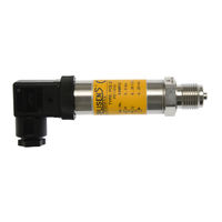
Aplisens PRE-28.Modbus User Manual (20 pages)
PRESSURE TRANSMITTERS
Brand:
Aplisens
| Category:
Accessories
| Size: 2 MB
Table of Contents
Table of Contents
3
1 Introduction
5
2 Safety Procedures
6
3 User Information
6
4 Transport and Storage
6
Transport
6
Storage
6
5 Warranty
7
6 Construction
7
Construction and Dimensions
7
Intended Use and Functions
7
Figure 2. Pressure Transmitter PRE-28, PRE-28 Ex Safety PRE-28.Smart, PR-29A, PR
8
Figure 4. PC(R)E-28, PC(R)E-28.Smart, PC(R)-29A, PC(R)-29B, PC(R)E-28.Modbus Rating Plate (Example)
10
Figure 5. Transmitter Installed in the Hazard Zones
11
Electrostatic Hazards
12
Figure 1. Pressure Transmitter PCE-28, PCE-28 Ex Safety, PCE-28.Smart, PC-29A, PC
8
Figure 3. Electrical Connections of the Transmitters PC(R)E-28, PC(R)E-28 Ex Safety
9
Identification
10
7 Using of Pce-28
11
Exd Versions in Accordance with ATEX
11
Exd Versions in Accordance with Iecex
11
8 Installation
12
General Recommendation
12
Installation in Areas with Dust Explosion Hazard
12
9 Electrical Connections
13
How to Connect Different Types of Transmitters
13
How to Connect Transmitters in Potentially Explosive Areas
14
Figure 8. Wiring Diagram Transmitters PC-29A, PR-29A, PC-29B, PR-29B
15
Figure 7. Wiring Diagram Transmitters PCE-28.Smart, PRE-28.Smart
15
Figure 6. Wiring Diagram Transmitters PCE-28, PRE-28, PCE-28 Ex Safety, PRE-28 Ex
15
Figure 9. PCE-28.Modbus, PRE-28.Mobdus Electrical Connection
16
Grounding
17
10 Technical Data
17
Electrical Parameters
17
Metrological Parameters
17
Permitted Environmental Conditions
17
Electromagnetic Compatibility, Immunity
17
Electromagnetic Compatibility, Emissions
18
Mechanical Immunity
18
Electrical Isolation
18
Insulation Strength
18
IP Protection Ratings
18
11 Inspections. Spare Parts
19
Periodic Inspections
19
Unscheduled Inspections
19
12 Scrapping, Disposal
19
Additional Information
19
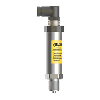
Aplisens PRE-28.Modbus User Manual (23 pages)
SMART PRESSURE AND DIFFERENTIAL PRESSURE TRANSMITTERS
Brand:
Aplisens
| Category:
Transmitter
| Size: 1 MB
Table of Contents
Table of Contents
5
Introduction
7
Purpose of the Document
7
Safety
7
Transport and Storage
8
Delivery Check
8
Transport
8
Storage
8
Guarantee
8
Identification
9
Manufacturer's Address
9
Transmitter Identification
9
CE Mark, Declaration of Conformity
9
Installation
10
General Recommendations
10
Installation Instructions for Transmitters with Distance Separators
10
Electrical Connection
11
Cable Connection to Transmitter Internal Terminals
11
Connection of Transmitters with PKD, PZ, SG, PM12 Type Connector (Cable Connection)
11
Transmitter Power Supply
11
Transmitter Supply Voltage
11
Specifications of Electrical Switching Terminals
12
Connecting of Transmitters in the MODBUS Network
12
Equipotential Bonding
13
Overvoltage Protection
14
Final Inspection of Cabling
14
Start-Up
14
Operation
15
MODBUS Register Layout
15
Pressure Unit Codes
16
Modbus Status Register Description
16
Error Codes Supported by Modbus
16
Maintenance
17
Periodic Inspections
17
Non-Periodic Inspections
17
Cleaning/Washing
17
Diagram Cleaning
17
Spare Parts
17
Repair
17
Returns
17
Scrapping, Disposal
18
History of Revisions
18
Explosion-Proof Device Manual EN.IX.PCE.PRE.28.MODBUS
19
Advertisement
Advertisement
Related Products
Aplisens PRE-28.Smart
Aplisens PRE-28 Ex Safety
Aplisens PCE-28.Smart
Aplisens PCE-28 Ex Safety
Aplisens PC-29A
Aplisens PC-29B
Aplisens PCE-28.Modbus
Aplisens PR-29A
Aplisens PR-29B
Aplisens PRE-28
Aplisens Categories
Transmitter
Measuring Instruments
Accessories
Monitor
Switch
More Aplisens Manuals
Login
Sign In
OR
Sign in with Facebook
Sign in with Google
Upload manual
Upload from disk
Upload from URL