Table of Contents
Advertisement
Quick Links
Advertisement
Table of Contents

Related Manuals for Nexans LANmark-OF ENSPACE


Summary of Contents for Nexans LANmark-OF ENSPACE
- Page 1 LANmark-OF ENSPACE Patch Panel PRODUCT INSTALLATION GUIDE September 2017 v1.0...
- Page 2 However, Nexans Data Center Solutions reserves the right to make changes or improvements to its products or its documentation as it deems necessary. Nexans Data Center Solutions is not responsible for how its products or its documentation is used in the field. In this document, no mention is made of rights with respect to trademarks or trade names which may attach to certain words or signs.
-
Page 3: Table Of Contents
General ................................4 Product references and features ........................5 LANmark-OF ENSPACE Patch Panel 1U 12x Modules Black (144 fibers) ........... 5 LANmark-OF ENSPACE Patch Panel 2U 24x Modules Black (288 fibers) ........... 6 LANmark-OF ENSPACE Patch Panel 4U 48x Modules Black (576 fibers) ........... 7 Optional modules and accessories ...................... -
Page 4: General
8 cage-nuts with screws (4U panel) 1 labeling strip All other accessories (e.g. adaptor modules) must be purchased separately. The product part numbers are available in the following pages of this document. LANmark-OF ENSPACE Patch Panel Installation Guide Page 4... -
Page 5: Product References And Features
Product references and features Product references and features LANmark-OF ENSPACE Patch Panel 1U 12x Modules Black (144 fibers) Part Number: NSPACE.PP1U The patch panel is fully assembled and includes a 19’’ chassis with a removable lid a hinged front cover 3 sliding trays that can be equipped with up to 3x 4 optional modules a sliding and tilting rear drawer equipped with loop rings and 2 supports for 20 mm (0.78”) -
Page 6: Lanmark-Of Enspace Patch Panel 2U 24X Modules Black (288 Fibers)
Product references and features LANmark-OF ENSPACE Patch Panel 2U 24x Modules Black (288 fibers) Part Number: NSPACE.PP2U The patch panel is fully assembled and includes a 19’’ chassis with a removable lid a hinged front cover 6 sliding trays that can be equipped with up to 6x 4 optional modules a sliding and tilting rear drawer equipped with loop rings and 2 supports for 20 mm (0.78”) -
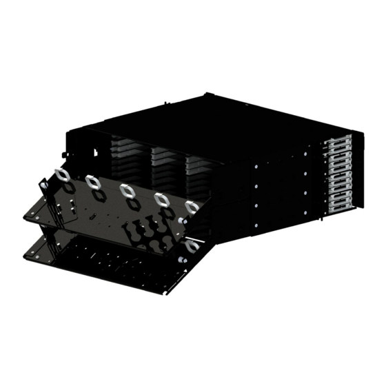
Page 7: Lanmark-Of Enspace Patch Panel 4U 48X Modules Black (576 Fibers)
Product references and features Note: A third support for glands can be ordered separately LANmark-OF ENSPACE Patch Panel 4U 48x Modules Black (576 fibers) Part Number: NSPACE.PPP4U The patch panel is fully assembled and includes a 19’’ chassis with a removable lid... - Page 8 Product references and features Two sliding and tilting rear drawers each equipped with loop rings and 2 supports for 20 mm (0.78”) glands Note: Two additional supports for glands can be ordered separately LANmark-OF ENSPACE Patch Panel Installation Guide Page 8...
- Page 9 Product references and features Note: The 4U patch panel is supplied with eight cage-nuts with screws LANmark-OF ENSPACE Patch Panel Installation Guide Page 9...
-
Page 10: Optional Modules And Accessories
MPO pre-terminated assemblies installation (MTP modules or MTP/LC modules) LC pigtail splicing (LC modules loaded with splice holders) Important Note LANmark-OF ENSPACE pre-terminated assemblies shall be selected to ensure compatibility with the ENSPACE patch panels and modules. LC adaptor modules... -
Page 11: Mtp Adaptor Modules
MTP Adaptor Modules Part Number Description NSPACE.PMTP2G LANmark-OF ENSPACE Adaptor Module 2x MTP Single-mode Key Up Key Down Green NSPACE.PMTP4G LANmark-OF ENSPACE Adaptor Module 4x MTP Single-mode Key Up Key Down Green NSPACE.PMTP6G LANmark-OF ENSPACE Adaptor Module 6x MTP Single-mode Key Up Key Down Green NSPACE.PMTP2A... -
Page 12: Mtp/Lc Modules
Optional modules and accessories Important notes about MPO polarity (MPO/MPO links) Nexans recommend the use of MPO pre-terminated assemblies with polarity method B when working with MPO/MPO links. Key up/Key down MPO adaptors are standard and shall be selected to maintain the polarity in most of the cases and especially when working with the polarity method B. -
Page 13: Pigtail Splicing
(see page 28). Important note As the available space dedicated to the storage of the fibers is limited in the modules, Nexans requires the use of ENSPACE pigtails. Tight buffer pigtails are not recommended, and will not be accepted for warranty claims. -
Page 14: Cable Glands
Fiber protection tube 3 mm (0.12”) Yellow 25 m (82’) (LMOF Cable Fan-Out) N890.051 Fiber protection tube 3 mm (0.12”) Aqua 25 m (82’) (LMOF Cable Fan-Out) Adhesive heat shrinkable sleeve Part Number Description N890.060 Adhesive heat shrinkable sleeve x10 (LMOF Heat Shrink Fan-out) LANmark-OF ENSPACE Patch Panel Installation Guide Page 14... -
Page 15: Fiber Optic Cable Stripping Tools And Accessories
Optional modules and accessories Fiber optic cable stripping tools and accessories Nexans recommends the OGCL N890.131 jacket stripping tool, adapted to the Micro Bundle cable construction, which has been developed to strip and cut the jacket longitudinally as shown below. -
Page 16: Splicing Accessories
LANmark-OF Pigtail OM4+ Maxistrip 50/125 12 colors N139.P012NaNbNcdeMSghxx.xS LANmark-OF Pigtail OM5 Maxistrip 50/125 12 colors Note: The colors match fiber colors according to ANSI/TIA-598-D (Blue, Orange, Green, Brown, Grey, White, Red, Black, Yellow, Violet, Pink, and Aqua) LANmark-OF ENSPACE Patch Panel Installation Guide Page 16... - Page 17 1. Tray labeling is located at the front of the fiber management bars. Labeling scheme: upwards from A to C (1U), A to F (2U) and A to M (4U) 2U ENSPACE panel 1U ENSPACE panel 4U ENSPACE panel LANmark-OF ENSPACE Patch Panel Installation Guide Page 17...
- Page 18 3. Use the side handles located on both sides of the trays to pull a tray out of the panel from the operational position to the patching position (also see the above image) LANmark-OF ENSPACE Patch Panel Installation Guide Page 18...
- Page 19 Check if the tabs are correctly engaged on each side of the cover. LANmark-OF ENSPACE Patch Panel Installation Guide Page 19...
- Page 20 Panel Operations 9. To open the front lid of the panel push down the two locks and pull to open. LANmark-OF ENSPACE Patch Panel Installation Guide Page 20...
-
Page 21: Installation Part 1 - Preparation Of The Patch Panel
They can be moved to the forward position (1) if the front space is limited in the rack or moved to one of the three most recessed positions (3, 4 or 5) if needed. LANmark-OF ENSPACE Patch Panel Installation Guide Page 21... - Page 22 Installation Part 1 – Preparation of the patch panel The “right” position is dependent on the available space between the 19” frame and the cabinet door and/or on the depth of the rack. LANmark-OF ENSPACE Patch Panel Installation Guide Page 22...
- Page 23 Termination from the front or from the rear The installation of the modules can be performed from the front or from the rear of the patch panel. Nexans recommends performing the initial installation from the rear, as it will ease the process (see picture).
-
Page 24: Installation Part 2A - Termination With Lc Pre-Terminated Assemblies
For pre-terminated fiber optic cable general pulling rules and pulling accessory removal procedure, please refer to the Nexans Installation Guide for Fiber Optic Cable and pre-terminated cable supplement. These documents can be viewed when logged into the NDS website (as explained on page 54). - Page 25 7. Coil the fibers on the base using the retention tabs (A) provided and insert connectors into the adaptors according to the color coding sequence. The result should be as indicated on the next pictures. LANmark-OF ENSPACE Patch Panel Installation Guide Page 25...
- Page 26 11. Lower the cover onto the module, lining up the side tabs to their corresponding holes, as illustrated on the picture. Note: Ensure that the fibers will not be pinched by the cover prior to locking in the cover. LANmark-OF ENSPACE Patch Panel Installation Guide Page 26...
- Page 27 See Annex A on page 54 for further details. Go to page 41 to continue the installation process: Installation Part 3 – Installation of the modules inside the patch panel. LANmark-OF ENSPACE Patch Panel Installation Guide Page 27...
-
Page 28: Installation Part 2D - Pigtail Splicing In Lc Modules
Important note Due to limited space, Nexans requires the use of Maxistrip pigtails. Tight buffer pigtails are not compatible. For the same reason, only cables containing 250 µm coated fibers shall be used (e.g. loose tube or Micro-Bundle constructions). - Page 29 (A). Notes The detailed cable jacket removal process is described in the Micro Bundle cable supplement of the Nexans Installation Guide for Fiber Optic Cable (see page 21). Recommended tools and accessories: see page 15. 4. Cut two, four, or eight pieces of protection tube according to the number of bundles contained into the cable.
- Page 30 Repeat the process until the entire length of micro-bundle is removed A remaining length of 10 to 15 mm (0.4” to 0.6”) of micro-bundle is acceptable Insert the micro-bundle into the position 20 AWG/0.80 mm of the stripping tool LANmark-OF ENSPACE Patch Panel Installation Guide Page 30...
- Page 31 11. Unscrew the gland, slide it forward until it is next to the sleeve, and tighten the gland in position. The fan-out is now ready to be terminated in the modules. LANmark-OF ENSPACE Patch Panel Installation Guide Page 31...
- Page 32 Termination of the fibers into the LC modules Important note Nexans recommends first installing all legs of the field-terminated assembly in their respective modules before proceeding to the installation of the modules into the patch panel. 1. Select the correct module depending on the type of fiber (MM or SM) and connector polishing (PC or APC).
- Page 33 Notes The fibers from the pigtails should make 2 loops in the module Nexans Maxistrip pigtails allow the removal of the 900 µm buffer in one operation after being cut to the right length. 6. Insert the 12 connectors into the adaptors according to the color coding sequence.
- Page 34 See Annex A on page 54 for further details. Go to page 41 to continue the installation process: Installation Part 3 – Installation of the modules inside the patch panel. LANmark-OF ENSPACE Patch Panel Installation Guide Page 34...
-
Page 35: Installation Part 2B - Termination With Mpo Pre-Terminated Assemblies In Mtp Modules
For pre-terminated fiber optic cable general pulling rules and pulling accessory removal procedure, please refer to the Nexans Installation Guide for Fiber Optic Cable and pre-terminated cable supplement. These documents can be viewed when logged into the NDS website (see page 21). - Page 36 6. Align the cable with the slot of the support and gently pushed it inside. The two legs inserted into the same dual MPO adaptor have to be inserted into the same slot of the back support (B). LANmark-OF ENSPACE Patch Panel Installation Guide Page 36...
- Page 37 The installation of the MTP adaptor module is completed. Repeat the process for every leg of the pre-terminated assembly. LANmark-OF ENSPACE Patch Panel Installation Guide Page 37...
- Page 38 See Annex A on page 54 for further details. Go to page 41 to continue the installation process: Installation Part 3 – Installation of the modules inside the patch panel. LANmark-OF ENSPACE Patch Panel Installation Guide Page 38...
-
Page 39: Installation Part 2C - Termination With Mpo Pre-Terminated Assemblies In Mtp/Lc Modules
For pre-terminated fiber optic cable general pulling rules and pulling accessory removal procedure, please refer to the Nexans Installation Guide for Fiber Optic Cable and pre-terminated cable supplement. These documents can be viewed when logged into the NDS website (see page 21). - Page 40 See Annex A on page 54 for further details. Go to page 41 to continue the installation process: Installation Part 3 – Installation of the modules inside the patch panel. LANmark-OF ENSPACE Patch Panel Installation Guide Page 40...
-
Page 41: Installation Part 3 - Installation Of The Modules Inside The Patch Panel
Important note: For shipping purposes the two glands supports are installed in their parking position (red circle). Both supports shall be reinstalled in the opposite direction or diagonal, even for the ones not in use (Green circle). LANmark-OF ENSPACE Patch Panel Installation Guide Page 41... - Page 42 (see the important note on the next page). When the support is correctly installed, push the four locks down. LANmark-OF ENSPACE Patch Panel Installation Guide Page 42...
- Page 43 It is recommend to first use the bottom right position (1). For supports having two rows of three holes (2U and 4U panels), first use the lower row according to the sequence shown on the picture. LANmark-OF ENSPACE Patch Panel Installation Guide Page 43...
- Page 44 Note: Ensure that either no cable is connected at the back of the module or that enough cable slack is available to pull the module out via the front. LANmark-OF ENSPACE Patch Panel Installation Guide Page 44...
- Page 45 Do not forget to push back the tray in their operational position before sliding back the rear drawer in its operational position or else the trays will prevent the rear drawer to reach its operational position. LANmark-OF ENSPACE Patch Panel Installation Guide Page 45...
- Page 46 Important note: The position of the cables/legs shall be maintained to ensure a smooth movement of the fibers when pulling the trays into their patching position and back to their operational position. 5. If needed prepare and install another assembly. LANmark-OF ENSPACE Patch Panel Installation Guide Page 46...
- Page 47 1 (Page 45) through 7. 9. For 1U panel when the installation of the modules on the three trays is completed go to step 12 (Page 49) to complete the installation. LANmark-OF ENSPACE Patch Panel Installation Guide Page 47...
- Page 48 11. Proceed to the installation of the next assemblies. Repeat the process from the step 1 (Page 45). LANmark-OF ENSPACE Patch Panel Installation Guide Page 48...
- Page 49 12. Gently slide the rear drawer back in its operational position and lock it using the two side locks (A) 13. Put the legs of the first column of modules inside the first loop ring (B). LANmark-OF ENSPACE Patch Panel Installation Guide Page 49...
- Page 50 Should a module require work, it has to be slid out from the rear of the panel. LANmark-OF ENSPACE Patch Panel Installation Guide Page 50...
- Page 51 The 4U panel is made up of an assembly of 2x 2U panels. Therefore, the process shall be repeated from step 1 to install the modules on the second group of 6 trays. LANmark-OF ENSPACE Patch Panel Installation Guide Page 51...
-
Page 52: Installation Part 4 - Finalization Of The Installation
The patch panel installation is now complete. Testing must be carried out in accordance with client requirements and Nexans requirements for warranty submission. Patch cords can now be installed. LANmark-OF ENSPACE Patch Panel Installation Guide Page 52... - Page 53 For example, there may be cases where the optical hazard identification labels must be placed on to racks and doors, so that they are observable even with the cabinet closed/locked. LANmark-OF ENSPACE Patch Panel Installation Guide Page 53...
-
Page 54: Annex A - Related Documents, Inspection, Cleaning, And Testing
In addition, there is also a General Installation guide (for both copper and fiber), which includes further information. Please note: The Nexans warranty may be invalidated if the cables have not been properly stored or handled according to Nexans Data Center Solutions (NDS) requirements. - Page 55 Annex A – Related documents, inspection, cleaning, and testing LANmark-OF ENSPACE Patch Panel Installation Guide Page 55...
-
Page 56: Annex B - Fiber Optic System Polarity
The boot color of the connectors shall match the colors indicated on the label located on the base of the LC adaptor module in front of the adaptors (see page 24). LANmark-OF ENSPACE Patch Panel Installation Guide Page 56... - Page 57 Aqua MPO/MPO fiber optic polarity The polarity is automatically maintained (method B or C) for Nexans MPO systems. NOTE: Always maintain an installation cleanliness practice! Close the drawer whenever you finish working on the panel and keep dust caps on the adaptors and patch cords when said items are not in use.
- Page 58 • all the connectors are clean Note: if the Nexans 25 year system warranty is required, testing and submission of results for certification is mandatory. Testing has to be performed according to the Nexans Installation Guide for Fiber Optic Cable, which is available from the Nexans website (see page 21).
-
Page 59: Annex C - Connection Scheme Of The Pre-Terminated Assemblies
Brown Brown Green Brown Gray Gray White Gray White White Gray White Black Black Black Black Yellow Yellow Violet Yellow Violet Violet Yellow Violet Pink Pink Aqua Pink Aqua Aqua Pink Aqua LANmark-OF ENSPACE Patch Panel Installation Guide Page 59... - Page 60 A label (B) is located on every leg at the rear of the fan- out. Each fiber is identified with a red or a black ring located on every duplex connector (A) LANmark-OF ENSPACE Patch Panel Installation Guide Page 60...
- Page 61 Black Black Black Yellow Yellow Violet Violet Violet Yellow Pink Pink Aqua Aqua Aqua Pink 900 μm End Leg Number 2 mm End Leg Numbers 7-12 13-18 19-24 25-30 31-36 37-42 43-48 LANmark-OF ENSPACE Patch Panel Installation Guide Page 61...
- Page 62 MPO/MPO pre-terminated assemblies with 2 mm fan-outs on both ends A label (A) is located on every leg at the rear of the MPO connector (A). Corresponding numbers are on the labels at both ends. LANmark-OF ENSPACE Patch Panel Installation Guide Page 62...
-
Page 63: Disclaimer
Nexans Data Center Solutions will not be held liable for any damage or injury to personnel, equipment, or business directly or indirectly as a result of using this document in part or in whole.
Need help?
Do you have a question about the LANmark-OF ENSPACE and is the answer not in the manual?
Questions and answers