
Related Manuals for Nexans Berk-Tek PowerGIG-OAC


Summary of Contents for Nexans Berk-Tek PowerGIG-OAC
- Page 1 PowerGIG‐OAC Installation Guide Self‐Enclosed PoE++ Switch, AC Powered, NA Installation Guide Page 1 of 44 BSP0402.C 33802 www.berktek.us ...
-
Page 2: Table Of Contents
PowerGIG‐OAC Installation Guide Table of Contents 1. Introduction ................................ 5 Ordering Information ............................ 6 Optional Accessories (Sold Separately) ...................... 6 Specifications ................................. 6 Environmental Specifications Applicable to PSE and PDs .................. 7 Feature Benefits .............................. 8 Components and Device View .......................... 9 Dimensions ................................ 11 Related Manuals .............................. 12 For More Information ............................ 12 2. Switch Installation ............................... 12 System Requirements ............................ 12 Package Contents .............................. 12 Unpacking ................................ 13 Cautions and Warnings ............................ 13 Warnings ‐ PoE ++ Family .......................... 13 Tools and Equipment ............................ 15 Safety and Labeling info from IEEE 802.3bt Standard .................. 15 General Safety .............................. 15 ... - Page 3 PowerGIG‐OAC Installation Guide Factory Reset Pushbutton (SW1)........................ 24 3. Applying Power .............................. 24 Power Connection Descriptions .......................... 24 Last Gasp................................ 24 AC Power Cords .............................. 24 Configuration Procedures ............................ 25 NFC Pre‐Configuration (Configuring the Switch Directly in the Box) .............. 25 Basic Installation Steps ............................ 25 Power Connection Procedures ........................ 26 PowerGIG‐FMK Fiber Tray Option ........................ 26 Boot Process .............................. 26 LED Locations .............................. 26 LED Descriptions .............................. 27 Removing the Switch ............................ 28 4. Additional Information ............................ 28 Q & A ................................... 28 Troubleshooting .............................. 30 PoE Troubleshooting ............................ 30 NFC Troubleshooting ............................ 31 Bluetooth Troubleshooting .......................... 31 PoE Modes, Compliance, Standards, and Troubleshooting ................ 32 PoE History .............................. 32 PoE Standards Comparison .......................... 32 PoE Classes .............................. 33 PoE Deployment Environments A and B ...................... 33 Environment B Requirements (from IEEE 802.3bt‐2018) ................ 34 Mode A vs. Mode B ............................ 34 ...
- Page 4 PowerGIG‐OAC Installation Guide Backward Compatibility ........................... 36 Compliance Information ............................ 36 FCC Regulations ............................... 36 Canadian Regulations ............................ 37 Service, Warranty and Support ........................... 38 Record Device and System Information ...................... 38 Contact Us ............................... 39 Codes and Standards ............................ 39 Glossary of Terms .............................. 40 Record of Revisions ............................. 43 Page 4 of 44 BSP0402.C 33802 www.berktek.us ...
-
Page 5: Introduction
PowerGIG‐OAC Installation Guide 1. Introduction The Berk‐Tek PowerGIG‐OAC Switch is a Layer 2 managed switch with (4) 10/100/1000BASE‐T PoE++ (IEEE 802.3bt) ports and (1) combination 10/100/1000BASE‐T RJ45 or 100/1000BASE‐X SFP uplink port (additional optional port available), that is ideal for use in security and surveillance, PoE lighting, digital signage and many other applications. A second 10/10/1000BASE‐T or 100/1000BASE‐X SFP/RJ‐45 combo port can be activated by installing an optional Combo Port Module (sold separately). The PowerGIG‐OAC switch is self‐enclosed in an outdoor NEMA 4X/IP66 rated enclosure with 6 kV surge protection on each port to protect against lightning or other surges in current, and additional fuse protection safeguards against unintentional intrusion from outside power lines, eliminating the need for external circuit cross protection. It can be mounted on a wall or side of a building, or optional brackets are available for mounting on a pole. The switch contains an AC‐powered power source (PSE) providing 45 W of power per port simultaneously on all four ports or up to 90 W on individual ports* (not to exceed 180 W total). (*Specific port configuration may apply; see Port Configuration on page 21.) Only ports 1 through 4 provide power; ports 5 and 6 do not offer PoE. More than one device using 90 W should be connected using alternate ports (i.e. no adjacent 90 W ports). Port 1 Port 2 Port 3 Port 4 Device Device Device Device Acceptable? Power Power Power Power (W) (W) (W) (W) 30 30 ... -
Page 6: Ordering Information
PowerGIG‐OAC Installation Guide Ordering Information Model Description AC‐powered self‐enclosed switch with (4) 10/100/1000BASE‐T PoE++ Ports and (1) Combo PowerGIG‐OAC Port [(1)10/100/1000BASE‐T RJ45 Port or (1) 100/1000BASE‐X SFP Port] Cord contains a NEMA 5‐15P plug (standard North American 15 A plug) Optional Accessories (Sold Separately) Accessory items are sold and shipped separately and are customer installed. Part Number Description PowerGIG‐CPM Combo Port Module to activate a 2nd combination 10/100/1000BASE‐T maintenance port or 100/1000BASE‐X combo uplink port. PowerGIG‐DIO Digital Input/Output Module with 4 optical isolators and a 12 V integral power source with 1,500 VDC isolation. PowerGIG‐PMK Pole Mount Brackets. NOTE: For poles ≥4” diameter, use pole straps (not provided) with bracket. For poles ≤4” diameter, use a 1‐3/8” x 1/4” U‐bolt (not provided) with bracket. PowerGIG‐FMK Fiber Management Kit; includes fiber management tray and alternative cable gland / inserts. Specifications IEEE 802.3, IEEE 802.3af, IEEE 802.3at, IEEE 802.3bt (Type 4, Class 8), IEEE 802.3ab, Standards IEEE 802.1 VLAN. (4) 10/100/1000BASE‐T RJ45 ports, (1) Combo port [(1)10/100/1000BASE‐T RJ45 Port or (1) 100/1000BASE‐X SFP Port] Ethernet Ports CAT 5e cable or higher recommended for 60 watts; ... - Page 7 PowerGIG‐OAC Installation Guide Operating: ‐22°F to +158°F (‐30°C to +70°C) (Inside Enclosure). External Operating: Environment ‐40°F to +122°F (‐40°C to +50°C). Storage: ‐40°F to +185°F (‐40°C to +85°C). Humidity: 5% to 95% (non‐condensing). Weight 4.8 lbs. [2.18 kg]. Emission EN55022, Class A, Immunity EN55024; meets Surge Protection as specified in GR‐1089 CORE Issue 4, ITU‐T K.21 6 kV on AC lines; NEMA 4X, Ingress Compliance Protection IP66; CE; IEC61000‐4‐2 (ESD); IEC61000‐4‐4 (EFT); IEC61000‐4‐5 (Lightning); Ul IEC60950‐1; IEC60950‐22; UL EN60950‐1; BLE 4.2; NFC ISO/IEC 14443A Part 2 and 3. NFC: NFC Form Type 2 Tag, ISO/IEC 14443A PowerGIG‐OAC: Handbook: Telcordia SR‐332, Issue 3. ENV: GB TEMP: 30.00 C CF: 1.00000 MODEL: Serial TELCORDIA CALCULATION METHOD: PartsCount (Method I) MTBF PIEL=7.5. 443,521 hours (Telcordia) Warranty 2 Years NFC Flex Stamp Antenna Specifications The antenna is a small flexible Near Field Communication (NFC) antenna built in to the inside of the front cover (shown below). It is based on well‐known antenna concepts and reliable technology, and it is RoHS compliant. Supported standards include ISO/IEC 14443 A / B (MIFARE), ISO/IEC 18092, JIS X 6319‐4/FeliCa), NFCIP‐1 / ECMA 3‐40, and NFC Forum Tag 4. It operates at a Frequency of 13.56 MHz. Specifications Applicable to PSE and PDs Port type: 10/100/1000BASE‐T Safety warnings: See Cautions and Warnings on page 13 PSE device PoE Type 4 ...
-
Page 8: Feature Benefits
PowerGIG‐OAC Installation Guide Feature Benefits Feature Benefit Saves time and labor expense by allowing laborers of any skill level to easily configure switch prior to Integrated NFC powering up and to repeat the configuration across multiple switches. Allows remote access to switch for troubleshooting Integrated BLE Antenna and changing settings, reducing time and hassles related to console cables and ladders or scissor lifts. Provides additional power source for auxiliary Auxiliary Port on PD equipment, reducing need for new power outlets. Provides mobile interface through the BLE and NFC Mobile App interface to connect to, configure, and diagnose the switch from a smartphone or tablet. Enables up to 45 watts of power per port simultaneously on all 4 ports or up to 90 watts per IEEE 802.3af/at/bt Compliant port on individual ports (not to exceed 180 watts total). Can be used to provide PoE to other devices or to PSE or PD Configuration receive and provide PoE where external power sources are not available. Protects switch from lightning or other surges in 6 kV Surge Protection current. Protects switch from harsh outdoor environments, NEMA 4X/IP66 Rated Enclosure including rain, dust, and insects and can be easily mounted on a pole, wall or building. Automatically restarts remote PDs reducing service PoE Auto Power Reset dispatches. ... -
Page 9: Components And Device View
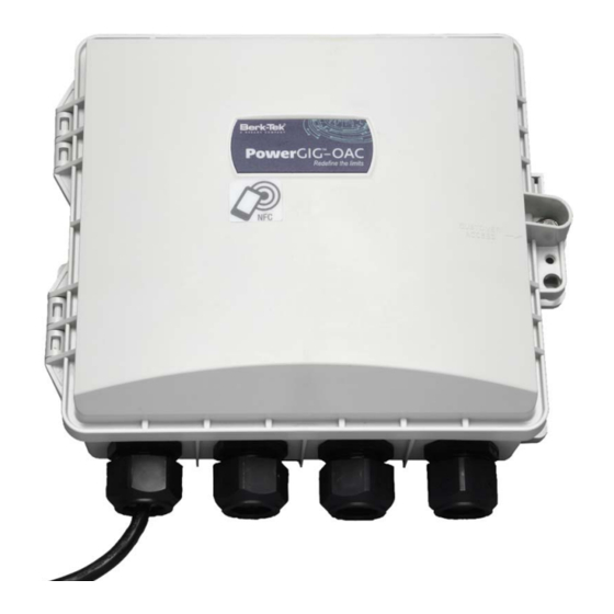
PowerGIG‐OAC Installation Guide Components and Device View Basic Switch Components Back View Page 9 of 44 BSP0402.C 33802 www.berktek.us ... - Page 10 PowerGIG‐OAC Installation Guide Components Page 10 of 44 BSP0402.C 33802 www.berktek.us ...
-
Page 11: Dimensions
PowerGIG‐OAC Installation Guide Dimensions Page 11 of 44 BSP0402.C 33802 www.berktek.us ... -
Page 12: Related Manuals
PowerGIG‐OAC Installation Guide Related Manuals The following manuals are available on the PowerGIG‐OAC product page, located at https://www.berktek.us/powergig. PowerGIG‐OAC Quick Start Guide PowerGIG‐OAC Installation Guide (this manual) PowerGIG‐OAC Operation Guide PowerGIG‐MobileAPP User Guide PowerGIG‐PMK Pole Mount Bracket Kit Installation Guide PowerGIG‐FMK Fiber Management Kit Installation Guide PowerGIG‐DIO Digital Input/Output Module Installation Guide PowerGIG‐CPM Combo Port Module Install Guide Release Notes (version specific) For More Information A printed Quick Start Guide is shipped with each unit. For PowerGIG Drivers, Firmware, etc. go to the Product Support webpage (logon required). For PowerGIG Manuals, Brochures, Data Sheets, etc. go to the Support Library (no logon required). For Industrial SFP Modules see Berk‐Tek Hardened SFP webpage for specific information. NOTE: Information in this document is subject to change without notice. Note that this manual provides links to third party web sites for which Berk‐Tek is not responsible. 2. Switch Installation This chapter provides system requirements, package contents, Cautions and Warnings, pre‐installation and Installation Guidelines, Hardware Install Procedures, Cabling, Grounding, Bonding, and Surge protection information. It is up to the installer to follow all switch installation procedures and to follow all local, province, state, territory, and national codes required per your local authority having jurisdiction. System Requirements Tablet: any with Android OS and NFC capability ... -
Page 13: Unpacking
PowerGIG‐OAC Installation Guide Please save the packaging for possible future use. One PowerGIG‐OAC Switch One Documentation Postcard One printed Quick Start Guide Hole plugs in a bag Unpacking Verify the contents. The switch can be configured directly in the box and unpacked at the install location. Cautions and Warnings Cautions indicate that there is the possibility of poor equipment performance or potential damage to the equipment. Warnings indicate that there is the possibility of injury to person. Cautions and Warnings appear here and may appear throughout this manual where appropriate. Failure to read and understand the information identified by this symbol could result in poor equipment performance, damage to the equipment, or injury to persons. See Electrical Safety Warnings on page 16 for Electrical Safety Warnings translated into multiple languages. Wiring methods shall be in accordance with all local codes and authorities having jurisdiction, such as the National Electrical Code/NFPA 70/ANSI within the USA. All units should be installed by trained service personnel. See UL 60950‐22 ‐‐ Information Technology Equipment ‐ Safety ‐ Part 22: Equipment to be Installed Outdoors. See IEC 62305‐1, NFPA 780, or CAN/CSA‐B72 for requirements for protection of the OUTDOOR EQUIPMENT against the effects of direct lightning strikes that are not covered by the UL standard. NOTE: Only qualified and trained service personnel (in accordance with IEC 60950 and local building codes) should install, replace, or service the equipment. Install the system in accordance with local, province, state, ... - Page 14 PowerGIG‐OAC Installation Guide WARNING: Before working on equipment that is connected to power lines, remove jewelry (including rings, necklaces, and watches). Metal objects will heat up when connected to power and ground and can cause serious burns or weld the metal object to the terminals. WARNING: Do not work on the system or connect or disconnect cables during periods of lightning activity. WARNING: Before performing any of the following procedures, ensure that power is removed from the DC circuit. WARNING: Read the installation instructions before you connect the system to its power source. WARNING: This equipment must be grounded. Never defeat the ground conductor or operate the equipment in the absence of a suitably installed ground conductor. Contact the appropriate electrical inspection authority or an electrician if you are uncertain that suitable grounding is available. WARNING: This unit might have more than one power supply connection. All connections must be removed to de‐energize the unit. WARNING: Only trained and qualified personnel should be allowed to install, replace, or service this equipment. WARNING: Ultimate disposal of this product should be handled according to all local, province, state, territory, and national laws and regulations. WARNING: To prevent the system from overheating, do not operate it in an area that exceeds the maximum recommended ambient temperature of 122°F (50°C). WARNING: Installation of the equipment must comply with local, province, state, territory, and national electrical codes. CAUTION: The installer should be using the appropriate cabling for the environment; it should be rated for an NEMA 4X/IP66 rated environment as applicable. Installation Guidelines When determining where to place the switch, observe these guidelines. Environment and Enclosure Guidelines: This equipment is considered Group 1, Class A industrial equipment, according to IEC/CISPR Publication 11. Without appropriate precautions, there may be potential difficulties ...
-
Page 15: Tools And Equipment
PowerGIG‐OAC Installation Guide For 10/100 and 10/100/1000 ports, cable length from switch to attached device cannot exceed 328 ft (100 m). Operating environment is within the ranges listed in Specifications on page 6. Keep the switch out of the sun if possible. o Try to install the switch so it is in the afternoon shade or under the eve of a building. o In the northern hemisphere, install the switch with the heat sink plate facing north. o In the southern hemisphere, install the switch with the heat sink plate facing south. Make sure ambient temperature does not exceed 122°F (50°C). Keep cabling away from sources of electrical noise, such as radios, power lines, and fluorescent lighting fixtures. Tools and Equipment Crimping tool (if hardwiring switch) Number‐2 Phillips screwdriver Flat‐blade screwdriver 3/8" nut driver for locking and unlocking enclosure Wire gland tool for tightening/loosening wire glands CAUTION: The input voltage source of the alarm output relay circuit must be an isolated source and limited to less than or equal to 36 VDC max. HIGH RISK ACTIVITIES DISCLAIMER: Components, units, or third‐party products used in the product described herein are NOT fault‐tolerant and are NOT designed, manufactured, or intended for use as on‐line control equipment in the following hazardous environments requiring fail‐safe controls: the operation of Nuclear Facilities, Aircraft Navigation or Aircraft Communication Systems, Air Traffic Control, Life Support, or Weapons ... -
Page 16: Network Safety
PowerGIG‐OAC Installation Guide Network Safety This subclause sets forth a number of recommendations and guidelines related to safety concerns. The list is neither complete nor does it address all possible safety issues. The designer is urged to consult the relevant local, province, state, territory, national, and international safety regulations to verify compliance with the appropriate requirements. LAN cabling systems described in this clause are subject to at least four direct electrical safety hazards during their installation and use. These hazards are as follows: a) Direct contact between LAN components and power, lighting, or communications circuits. b) Static charge buildup on LAN cabling and components. c) High‐energy transients coupled onto the LAN cabling system. d) Voltage potential differences between safety grounds to which various LAN components are connected. Such safety hazards should be avoided or appropriately protected against for proper network installation and performance. In addition to provisions for proper handling of these conditions in an operational system, special measures should be taken to verify that the intended safety features are not negated during installation of a new network or during modification of an existing network. Patch Panel Considerations It is possible that the current carrying capability of a cabling cross‐connect may be exceeded by a PSE. The designer should consult the manufacturer’s specifications to verify compliance with the appropriate requirements. Electromagnetic Emissions The PD and PSE powered cabling link shall comply with applicable local, province, state, territory, and national codes for the limitation of electromagnetic interference. Temperature and Humidity The PD and PSE powered cabling link segment is expected to operate over a reasonable range of environmental conditions related to temperature, humidity, and physical handling. Specific requirements and values for these parameters are beyond the scope of the standard. Electrical Safety Warnings Electrical Safety ... -
Page 17: Grounding/Bonding/Surge Protection/Fuse Protection
PowerGIG‐OAC Installation Guide Sicurezza elettrica IMPORTANTE: questa apparecchiatura deve essere installata rispettando le norme di sicurezza. Elektrisk sikkerhet VIKTIG: Dette utstyret skal installeres i samsvar med sikkerhetsregler. Segurança eléctrica IMPORTANTE: Este equipamento tem que ser instalado segundo as medidas de precaução de segurança. Seguridad eléctrica IMPORTANTE: La instalación de este equipo deberá llevarse a cabo cumpliendo con las precauciones de seguridad. Elsäkerhet OBS! Alla nödvändiga försiktighetsåtgärder måste vidtas när denna utrustning används. Grounding/Bonding/Surge Protection/Fuse Protection Surge Protection Security cameras can act as lightning rods, drawing the voltage through the copper cabling to the networking equipment. If a lightning strike hits within a few hundred feet of a cable, it can produce thousands of volts and several million watts. Without proper protection, this can seriously damage or destroy networking equipment. In a networked video surveillance system, the IP‐based cameras can run on a dedicated video network or connect directly back to the data center or telecom room. On a dedicated video network, a high‐voltage surge can cause extensive damage to sensitive electronics (e.g. Ethernet switches, network servers, and storage devices). The surge can cause serious damage to mission‐critical equipment if the IP cameras are connected to the main production network. Each of the PoE port interfaces’ four data pairs, as well as the included combo port’s RJ45 interface, are fused and have gas discharge tubes and other solid state devices to meet the outdoor exposure requirements for power faults and lightning protection required in the following standards. No other external protection devices are required. Meets Surge Protection as specified in GR‐1089 CORE Issue 4 ITU‐T K.21 and YD/T 993‐1998 (Enhanced Requirements) IEC61000‐4‐5 (Class 0‐4) IEC61000‐4‐2 (ESD) & 4‐4 (EFT) WARNING: The surge protection built into the PowerGIG‐OAC is not intended to eliminate the need for a UL497 ... -
Page 18: Cable And Cabling
PowerGIG‐OAC Installation Guide 2. Ground the switch via the AC cord before connecting other cables. 3. Disconnect the grounding only after disconnecting all other cables. Pole Mount Installation For mounting to a pole, use the optional Pole Mount Bracket Kit (part number PowerGIG‐PMK) and follow instructions provided with the kit. Mounting straps or U‐bolts are required to secure brackets to pole (installation‐specific and not provided). Cable and Cabling The 802.3bt standard allows Cat 5e for 60 W but requires minimum Cat 6 cable for 90 W. You can use Category 5e or 6A cable, but remember: o Cat 6A has larger bundle sizes, o Cat 6A can go longer reaches with PoE, and o Category 6A is 4.3 W more efficient per link. For Cat 5e use 4‐pair Category 5e or higher. Use UV‐resistant Cat 5e, Cat 6, or Cat 6A cable. If the channel is standards compliant to its appropriate category standard at 100 meters or less, the PD will get the power it needs. Standards governing cabling PoE: o IEEE 802.3bt‐2018: overall standard governing equipment and cabling. o TIA TSB‐184‐A: Technical Service Bulletin on “Guidelines for Supporting Power Delivery Over Balanced Twisted‐Pair Cabling”. o ISO/IEC TR‐29125 and CENELEC TR 50174‐99‐1 (International cabling guidelines for PoE++). o ANSI/TIA‐568.2‐D (familiar standard covering cabling performance). o IEC 60512‐99‐002 (standard for connectivity with engaging / disengaging PoE). ... - Page 19 PowerGIG‐OAC Installation Guide If using more than one 90 W port, then alternate ports (i.e. no adjacent 90 W ports). Ports 5 and 6 do not provide PoE of any type. Wire Gland Plug Kit Various wire gland inserts are provided. To maintain NEMA/IP rating, be sure to use the most appropriately sized for your cable and fill unused holes with the hole plugs provided. Page 19 of 44 BSP0402.C 33802 www.berktek.us ...
- Page 20 PowerGIG‐OAC Installation Guide Wire Gland Plug Kit NOTE: You can use ¾” water proof whip (rigid or flexible) in place of wire gland inside or outside a building. NOTE: Split gland is easiest to use. Press finger or tool through and press split gland out. NOTE: Install cabling before connecting power. NOTE: Try to keep the switch out of direct sunlight and try to maximize space around switch to maximize air flow. Grommet sizes available for the entrance locations of the fiber and cables: There are (2) 0.275 in. (7 mm) holes in each wire gland standard on the switch. The Fiber Management Kit (part number PowerGIG‐FMK) comes with (1) replacement wire gland with a single oval shaped hole to accommodate max 0.137 in. X 0.610 in. (3.5 mm x 15.5 mm) sized fiber cable and (1) replacement wire gland with a single round hole to accommodate a range of 0.251 in. to 0.488 in. (6.4 to 12.4 mm) fiber cable. If using liquid tight flexible conduit, a Trade Side 3/4” connector should be used. The grommets are not gel filled. As you tighten the wire gland nut, the insert squeezes tight around the cable. This meets IP67 rating. Recommended cables Recommended Berk‐Tek Indoor/Outdoor Fiber Optic Cables Part Numbers ICP002EB3010/25‐I/O‐C4(AQU): interconnect plenum indoor/outdoor cable, two strands of multimode (OM3) ICP002AB0707‐I/O‐C4(YEL): interconnect plenum indoor/outdoor cable, two strands of single‐mode (OS2) ICP004EB3010/25‐I/O‐C4(AQU): interconnect plenum indoor/outdoor cable, four strands of multimode (OM3) ICP004AB0707‐I/O‐C4(YEL): interconnect plenum indoor/outdoor cable, four strands of single‐mode (OS2) PDP006EB3010/25‐I/O‐C4(AQU): interconnect plenum indoor/outdoor cable, six strands of multimode (OM3) Page 20 of 44 BSP0402.C 33802 www.berktek.us ...
-
Page 21: Flexible Metal Conduit (Fmc)
PowerGIG‐OAC Installation Guide PDP006AB0707‐I/O‐C4(YEL): interconnect plenum indoor/outdoor cable, six strands of single‐mode (OS2) These cables can be installed in indoor and outdoor installations. If placed underground, the cable must be placed into conduit that is located below the frost line. This cable cannot be aerially lashed. Data sheets can be found here. For other installations, please go to www.berktek.us. Recommended Nexans Industrial Solutions indoor and outdoor copper cables Cable Family Type OD (inches) Flame Rating/Environment Field Installable Plug LANmark‐A689‐RJU‐PKB LANmark‐A689 Category 6 0.265 CMR/CMX Outdoor (81000743) This cable does not contain any gel. It is CMR rated for indoor locations and can be installed in damp location installations. This cable should not be aerially lashed or buried at all. The field installable plug requires the crimping tool part number 2990003‐01. Recommended Berk‐Tek outside plant copper cables Cable Family Type OD (inches) LANmark‐1000 OSP Category 6 0.245 LANmark‐6 OSP Category 6 0.250 These cables are gel‐filled. They are designed for wet location installations, which can include aerial or buried in conduit underground. Flexible Metal Conduit (FMC) Short segments of FMC are often used as circuit pigtails between junction boxes and fixtures. Whip assemblies ... - Page 22 PowerGIG‐OAC Installation Guide Port 5 is a combo 10/100/1000BASE‐T or a 100/1000BASE‐X uplink port. It can either be used as a copper or fiber port. It does not supply PoE power. Port 6 becomes available when you add either the optional Combo Port Module (PowerGIG‐CPM), which allows you to activate a second combo 10/100/1000BASE‐T maintenance port or second 100/1000BASE‐X uplink port. Port 6 does not supply PoE power but can be used for such activities as aiming cameras or connecting a secondary data source. The optional Combo Port Module has secondary surge protection, but not primary or cross power. If using the optional PowerGIG‐CPM outside the switch enclosure, users must provide the primary or cross power protection. NOTE: If using more than one 90 W port, then alternate ports (i.e. no adjacent 90 W ports). Ports 5 and 6 do not provide PoE of any type. Console Port The Console port provides an RJ45 connector for serial connection to a network PC running a terminal emulation package such as PuTTY. See the PowerGIG‐OAC Operation Guide for CLI command information. SFP Installation Each of the PowerGIG‐OAC versions has one combo 10/100/1000BASE‐T, RJ45, or 100/1000BASE‐X SFP port. You can install or remove a SFP (sometimes known as mini‐GBIC) module from a SFP port without having to power off the switch. The SFP cages are oriented with the bottom SFP cage used for the included combo port (port 5) and the top SFP cage used for the optional second combo port operation (port 6). On the bottom SFP cage (port 5) insert the SFP with the label down. On the top SFP cage (port 6) insert the SFP with the label up. NOTE: The SFP ports must use industrial‐rated optical transceiver product, Rated 3.3 Vdc, Laser Class 1. See the SFP’s manual for specific cautions, warnings, and instructions. Industrial SFP Modules: Berk‐Tek offers a full line of small form factor pluggable (SFP) modules. Industrial rated models must be used for outdoor switch installation. See Berk‐Tek Hardened SFP webpage for more SFP ...
- Page 23 PowerGIG‐OAC Installation Guide The Fiber Optic Association (FOA) is an international non‐profit educational organization chartered to promote professionalism in fiber optics through education, certification, and standards. See the FOA User's Guide To Fiber Optic System Design and Installation for fiber optics/fiber cabling issues. The FOA's Guide To Fiber Optics & Premises Cabling includes almost a thousand pages of materials created by the FOA covering the basics to advanced topics on fiber optics and premises cabling. To install an SFP in the PowerGIG‐OAC: 1. Position the SFP device at the proper installation slot, with the label facing correctly (see SFP orientation above). 2. Carefully slide the SFP device into the slot, aligning it with the internal installation guides. 3. Ensure that the SFP device is firmly seated against the internal mating connector. 4. Connect the fiber cable to the fiber port connector of the SFP device. SFP Removal CAUTION: Be careful when removing the SFP from a device. Some SFP transceiver module temperatures may exceed 160°F (70°C) and be too hot to touch with bare hands. NOTE: Do not remove and replace the SFP modules more often than necessary; excessive SFP removing and replacing can shorten the SFPs useful life. 1. Disconnect any fiber that is connected to the SFP module. 2. Push back the locking lever on the SFP. 3. Pull out SFP module. Page 23 of 44 BSP0402.C ...
-
Page 24: Pcb Configuration (Reset Button, Leds, Etc.)
PowerGIG‐OAC Installation Guide PCB Configuration (Reset button, LEDs, etc.) Factory Reset Pushbutton (SW1) The Factory Reset button is located in the lower left corner of the switch, right above the far left Wire Gland. It can be used as follows: Short press (less than 10 seconds) will issue a power down (system) reset. Long press (more than 10 seconds) to reset to factory defaults. If the reset is unsuccessful the message “Command failed" displays in the Web UI. If the reset is successful, the message "Set to factory settings" displays in the Web UI. NOTE: You can also perform a Restart or Reset from the Web UI. NOTE: You can perform a Restore system configuration (copy command) or Reload (reload command) from the CLI. 3. Applying Power Power Connection Descriptions AC‐powered power source (PSE) providing 45 watts of power per port simultaneously on all four ports or up to 90 watts on individual ports (specific port configuration may apply) (not to exceed 180 watts total). Power to the PowerGIG‐OAC is via a built‐in 12‐foot 16 AWG power cable with a 3‐prong plug. The unit has an internal 550 W power supply (90‐264 VAC, 47‐63 Hz). The AC input is via a hardwired AC cord or hardwired into AC mains via customer supplied conduit and conduit connectors. NOTE: Constant power must be provided for the real time clock; the switch has a super Cap that provides backup to the real time clock for up to 12 hours. Beyond that, battery backup must be provided externally through a UPS. Last Gasp In the event of power failure, the switch will send an SNMP trap notification of the power failure. The notification will only be sent on switch port 5. The 'Last Gasp' feature provides 10 W for 5 ms; however, PoE power is not protected on failure. ... -
Page 25: Configuration Procedures
PowerGIG‐OAC Installation Guide AC Power Cord Specifications Ratings o Voltage: 300 VAC. o Temperature: 105 deg. C. o Flame Rating: VW‐1. Conductor o Wire Size: 18‐AWG. o Number: 3‐Conductor. o Material: Bare Copper. o Stranding: 41/0.16 mm. Insulator o Material: PVC. o Color: White, Black, Green/Yellow. o Nominal Thickness: 0.0149 in. (0.38 mm). o Outer Diameter: 0.0787 in. (2.0 mm). Outer Jacket o Material: PVC. o Color: Black. o Nominal Thickness: 0.0299 in. (0.76 mm). o Diameter: 0.0787 in. (2.0 mm). ... -
Page 26: Power Connection Procedures
PowerGIG‐OAC Installation Guide 6. Connect PDs to switch; run Ethernet cable from switch PSE ports 1‐4 to devices to be connected and powered. a. Note if connecting multiple 90 W devices, it is recommended that those devices be connected to ports that are separated from one another (i.e. no adjacent 90 W ports). Ports 5 and 6 do not provide PoE of any type. 7. Connect power to switch: a. Plug in switch to AC outlet i. If hard wiring, cut off power connector and: 1. Connect to junction box (if allowed); 2. run cable through conduit and hard wire to junction box (if code requires). 8. Close switch door and lock enclosure using hex driver or tool. 9. When successfully installed, configure ports, power, etc. via BLE, CLI or Web UI. See the Operation Guide. Power Connection Procedures Plug into approved AC outlet using supplied AC power cord. If the application calls for routing through conduit or hard wiring, the AC plug can be cut off of the supplied cord and hard wired into junction box if code allows. NOTE: The provided wire gland can be replaced with a conduit connector. Berk‐Tek does not recommend taking the protective cover off of the switch to re‐wire. The AC cable is already connected to the Ground Post in the switch at the factory. PowerGIG‐FMK Fiber Tray Option A fiber tray option is available for terminating the fiber cable. See the PowerGIG‐FMK Fiber Management Kit Install Guide for details. Boot Process After power up, the PowerGIG‐OAC can take about 1‐1/2 minutes to boot up. The LED indicators on the PCB will light after about a minute and a half. ... -
Page 27: Led Descriptions
PowerGIG‐OAC Installation Guide LED Descriptions LEDs are provided to report PoE activity, link activity, system readiness, and switch power and BLE pairing information as shown and described below. 1. PSE Controller LED: off = not ready; on (blue) = ready. 2. PoE Activity LEDs PSE Port 1: off = no power; amber = 2‐pair powered; green = 4‐pair powered. PSE Port 2: off = no power; amber = 2‐pair powered; green = 4‐pair powered. PSE Port 3: off = no power; amber = 2‐pair powered; green = 4‐pair powered. PSE Port 4: off = no power; amber = 2‐pair powered; green = 4‐pair powered. 3. Link Activity: amber LEDs from top to bottom: Port 1: off = no activity; on = link activity. Port 2: off = no activity; on = link activity. Port 3: off = no activity; on = link activity. Port 4: off = no activity; on = link activity. Port 5 (included combo port): off = no activity; on = link activity. Port 6 (optional combo port): off = no activity; on = link activity. CPU Port: off = no CPU activity; on = CPU activity. 4. CPU heart beat Page 27 of 44 BSP0402.C 33802 www.berktek.us ... -
Page 28: Removing The Switch
PowerGIG‐OAC Installation Guide The blue heartbeat LED and the green LED right below it flash in unison when the system has successfully booted and is not in the middle of a firmware upgrade. The green BLE LED is lit most of the time, with a slight flicker to indicate when the BLE radio is ready to pair with a smart device running the Switch Manager app. The green LED turns off during boot, then changes to heartbeat pattern (along with the blue LED) once initialization is complete. (Currently, there is no way to know via the LEDs that a firmware upload is in process.) 5. Switch LEDs Power: off = no power; on (amber) = powered. BLE Ready state: constant off = not ready; on (green but blinking off about every 10 seconds) = ready. BLE Pairing state: off = not paired; on (blue) = paired. Removing the Switch CAUTION: Disconnect the grounding only after disconnecting all other cables. To remove (uninstall) the switch: 1. Disconnect the data cables. 2. Disable the supply voltage. 3. Disconnect the grounding connection (may be as simple as disconnecting the power plug). 4. Unmount the switch. 5. Place the switch in the original shipping package. 4. Additional Information Q & A Q1: What are some applications for using the switch? A1: The switch can be used to connect and provide power to advanced security and surveillance cameras such as PTZ, dome, and high‐speed cameras; PoE lighting; digital signage; and building access and control systems. Q2: How much power does the switch provide? A2: Up to 90 W per port are available on any of the first four ports; up to 180 W total on all ports simultaneously. Ports 5 and 6 (if installed) do not provide PoE of any type. Q3: Does the switch have a fiber port? A3: The switch comes with (1) 10/100/1000BASE‐T RJ45 or 100/1000BASE‐X Combo Port. In addition, an ... - Page 29 PowerGIG‐OAC Installation Guide A6: When the NFC‐enabled device (smartphone or tablet) and the NFC “tag” or antenna on the switch are in close proximity, a magnetic field is formed and the power from that magnetic field uses modulation to transfer data. The NFC antenna/tag contains a nonvolatile EEPROM which retains the data transferred from the smartphone or tablet even after it moves out of proximity, and the configuration is transferred into the switch’s memory once the switch is fully powered up. Q7: What does the BLE feature do? A7: The Bluetooth Low Energy feature allows remote access to the switch without having to physically connect with a cable, so monitoring and troubleshooting and changes can be made prior to leaving the job site or after ladders or scissor lifts have been removed. The maximum range is approximately 328 feet (100 meters); local environmental factors (such as trees, building materials, etc.) can limit this distance. Q8: Are the BLE and NFC features safe and secure enough for my network? A8: NFC is considered very secure and is frequently used for contactless payments (e.g. Apple Pay). A secure channel is established and uses encryption for sending sensitive information. However, we always recommend users have antivirus software and passwords on their devices in case they are lost or stolen. BLE uses Advanced Encryption Standard (AES), 128/256, SHA‐1, SHA‐2 (SHA‐224 and SHA‐256) and Elliptic Curve Cryptography (ECC) encryption. It uses an authenticated encryption algorithm designed to provide both authentication and confidentiality. AES was adopted by the US Government in 2002 and is used worldwide. Q9: Does the switch need to be mounted in a cabinet? A9: No, the switch is housed in its own NEMA 4X/IP66 rated enclosure and can be wall‐mounted or pole mounted (requires optional brackets). It also includes 6 kV surge protection for lightning protection or other current surges and additional fuse protection to protect from unintentional intrusions from outside power lines. Q10: Are there any management features? A10: Yes, the switch IMS features include Auto Power Reset (APR) to re‐boot remote devices and reduce service dispatches. The switch has port management and PoE management, including the ability to preserve and schedule power. Other IMS features include management of devices and cable diagnostics for finding cable faults or connection issues. Q11: What is the app used for? A11: The PowerGIG‐MobileAPP interfaces with the NFC and BLE features to allow switch configuration, remote diagnosis and troubleshooting without having to climb a ladder or scissor lift to connect to the switch. Q12. What is the Digital I/O feature used for? A12. The digital input/digital output has four optical isolators independently configurable as either inputs or ...
-
Page 30: Troubleshooting
PowerGIG‐OAC Installation Guide Troubleshooting The BLE app, Console Port or Web UI can be used for troubleshooting the switch. 1. Verify that your model supports the function you are trying. See Feature Benefits on page 8. 2. Check the Release Notes for any known issues. 3. Check the PowerGIG‐OAC webpage for the more current firmware. 4. Verify the System Requirements on page 12. 5. Verify the Cautions and Warnings on page 13. 6. Verify the Cable and Cabling on page 18. 7. Monitor and document the LEDs described on page 26. 8. Make sure related hardware (Cameras, WAPs, SFPs, Injectors, etc.) is connected and operating correctly; see the related device manuals and helps. 9. Make sure related applications (BLE, NFC, etc.) are configured and running properly. 10. Make sure related options (e.g. PowerGIG‐DIO, PowerGIG‐FMK, PowerGIG‐CPM) are installed and operating properly; see the related option kit install guide. 11. If you suspect a PoE problem, see PoE Modes, Compliance, Standards, and Troubleshooting on page 32 below. 12. If you suspect a NFC problem, see NFC Troubleshooting on page 31. 13. If you suspect a Bluetooth problem, see Bluetooth Troubleshooting on page 31. 14. Contact TEK Support; see Contact Us on page 39. PoE Troubleshooting 1. Get as much detail as possible regarding the symptom, including any system messages from the PoE switch. For example, does a PD not power up at all, or does it power up briefly and then power down? ... -
Page 31: Nfc Troubleshooting
PowerGIG‐OAC Installation Guide Check for error messages reported by the switch at the same time of the disconnect. 12. Verify that an IP camera is not losing access just before a reload occurs (a network problem, not a PoE problem). 13. Pre‐standard and post‐standard IP camera may use different detection and connect/disconnect methods. NOTE: PD detection occurs when an Ethernet device is first connected to a PoE port. If a non‐PoE device is connected to a PoE port, detection is deactivated. If the non‐PoE device is later disconnected and replaced by a PD, the switch may not detect it immediately. 14. Verify that the PD is not causing an overcurrent condition on the port. Specifically: does the IP camera WAP, or lighting initially power on and then disconnect? If so, the problem may be an initial current surge that exceeds a current‐limit threshold for the switch port. Some PDs may have excessive “surge in” current when first connected to a PoE port. The switch initially provides power to the port, and then quickly removes power due to a momentary overcurrent condition. The PD starts to power up, but then quickly powers down. 15. The PowerGIG‐OAC has voltage and current regulators that detect an overcurrent threshold and disconnect power from the line. This prevents excessive current from being delivered by the PoE port, which could possibly result in damage to port‐level components. NFC Troubleshooting Check if you have NFC. Not all phones and tablets have NFC. Check your phone’s Settings menu: 1. On your Android device, tap on Settings. 2. Tap More. 3. Scroll down and you should see NFC and Android Beam options. WARNING: Your phone or tablet may have different steps to activate NFC; please see the user manual for your device. If your device has NFC, check that the chip and Android Beam are activated so that you can use NFC: 1. Go to Settings > More. 2. Tap on the NFC switch to activate it. The Android Beam function will also automatically turn on. 3. -
Page 32: Poe Modes, Compliance, Standards, And Troubleshooting
PowerGIG‐OAC Installation Guide Once paired, the switch configuration should remain highlighted in green until you Disconnect. If you lose pairing, try closing out of the PowerGIG‐MobileAPP, go back into the app and pair again. 6. Contact TEK Support if you still have any of these issues: You can’t turn on Bluetooth or the setting is grayed out. You can’t connect any Bluetooth accessories with your device. The accessory manufacturer confirmed that your accessory is working correctly. PoE Modes, Compliance, Standards, and Troubleshooting The switch is a Type 4 device (Class 8) that supports IEEE 802.3af/at/bt Power‐over‐Ethernet. PoE History PoE first emerged to solve the problem of powering Voice over Internet Protocol (VoIP) phones. PoE gained momentum in 2001 and 2002, when WAP makers, and other manufacturers took advantage of the technique. IEEE 802.3af can use a single standard RJ45 connector and Cat 5 (or even Cat 3) cable. PoE+ (PoE Plus) provides extended support for new end devices with higher power requirements. The IEE 802.3at standard provides up to 30 W of power to include newer end devices such as IEEE 802.11n wireless access points, surveillance cameras, etc. PoE++ (IEEE 802.3bt): As manufacturers continued to advance the use of PoE, another option became available for PoE with greater output. PoE++ delivers up to 90 watts of power using the 802.3bt standard. PoE++ is delivered using 4 Pairs. PoE++ is ideal for IP surveillance cameras that require more throughput or various other equipment such as LCD displays, computer workstations, and biomedical equipment. Minimum cable type is Cat 5e; it is recommended Cat 6A cabling. PoE Standards Comparison IEEE 802.3af PoE IEEE 802.3at PoE+ IEEE 802.3bt PoE++ IEEE 802.3bt PoE++ Property Type 1 Type 2 Type 3 ... -
Page 33: Poe Classes
PowerGIG‐OAC Installation Guide Type 1: Also known as PoE, 2‐pair PoE. Related standard: IEEE 802.3af. Maximum power to port: 15.4 W. PoE Type 1 utilizes two pairs to connect many types of lower‐powered devices to the network. Based on the initial IEEE 802.3af‐2003 standard, it provides up to 15.4 W of DC power to each PoE port (up to 12.95 W of power for each device). PoE Type 1 can support devices such as VoIP phones, sensors/meters, wireless access points with two antennas and simple, static surveillance cameras (no pan, tilt or zoom). Type 2: Also known as PoE+ and PoE Plus. Related standard: IEEE 802.3at. Maximum power to port: 30 W. Higher‐powered devices are connected to the network using PoE Type 2, based on the IEEE 802.3at‐2009 standard. It is backward compatible (supports PoE Type 1 devices) and provides 30 W of DC power to each PoE port (up to 25.5 W of power for each device). PoE Type 2 can support devices such as more complex surveillance cameras that pan, tilt or zoom, as well as wireless access points with six antennas, LCD displays, biometric sensors, and tablets. Type 3: Also known as 4‐pair PoE, 4P PoE, PoE++, and UPOE. Related standard: IEEE 802.3bt. Maximum power to port: 60 W. PoE Type 3 uses all four pairs in a copper cable, based on the IEEE 802.3bt‐2018 standard. It provides 60 W of DC power to each PoE port (up to 51 W of power for each device). PoE Type 3 can support devices such as videoconferencing system components and building management devices. Type 4: Also known as higher‐power PoE. Related standard: IEEE 802.3bt. Maximum power to port: 90 W. Growing power requirements of network devices are pushing the need for higher power delivered through network cabling – which is where PoE Type 4 comes into play. It provides up to 90 W of DC power to each PoE port (up to 71 W of power for each device – see IEEE 802.3bt Annex Clause 145.3.8.2.1 ‐ Input average power exceptions). PoE Type 4 can support devices such as laptops and TVs. PoE Classes PoE Classification is where the PSE detects the PD’s power requirements by using Physical Layer Classification or LLDP. The IEEE 802.3bt standard specifies mutual identification to address four‐pair operation. Additional clauses were added, defining the following: PSE Output Power PD Input Power PD Class Type Standard (W) (W) 0 ... -
Page 34: Environment B Requirements (From Ieee 802.3Bt-2018)
PowerGIG‐OAC Installation Guide Environment A: when both PSE and PD are located indoors, inside the same building. In this environment, there has to be electrical isolation between the PoE circuitry and the data circuitry inside a PSE. Multi‐port PSE’s can all share the same ground isolation. Environment A is therefore an indoor PSE – indoor PD environment (a.k.a. indoor/indoor). Environment B: when the PSE and PD are not located in the same building. In this environment there needs to be electrical isolation between PoE and data, as well as between every port in a multi‐port PSE. In summary, the PD‐PSE environment is one of these three combinations: 1. PoE Source is indoor, PD is indoor (Env. A) 2. PoE Source is indoor, PD is outdoor (Env. B) 3. PoE Source is outdoor, PD is outdoor (Env. B) Option 3 is the most challenging environment since both the PD and PSE are installed outdoors. The switch is an indoor or outdoor device. It can be used with outdoor devices such as outdoor IP cameras or outdoor Wi‐Fi APs. Environment B Requirements (from IEEE 802.3bt‐2018) The requirements for interconnected electrically conducting link segments that are partially or fully external to a single building environment may require additional protection against lightning strikes or other hazards. Protection requirements for such hazards are beyond the scope of this standard. Guidance on these requirements may be found in Clause 6 of IEC 60950‐1 and throughout IEC 62368‐1, as well as any local, province, state, territory, and national codes related to safety. This requirement can be found in clause 145.4.1.1.2 in IEEE 802.3bt. Mode A vs. Mode B Alternative A, also known as Mode A, uses the data pairs of an Ethernet link to deliver power. Data Pairs include pins 1,2 and 3,6. PSEs using Mode A supply a positive voltage to pins 1 and 2. Alternative B, also known as Mode B, uses the spare pairs to deliver power. Spare Pairs include pins 4,5 and 7,8. 802.3af/at Standard “compliant” vs “compatible” PDs Knowing the difference between PoE “compliant” devices and “compatible” devices can help avoid interoperability and connectivity issues. Compliant and compatible PoE devices are not held to the same 802.3af/at standard: 802.3af/at “compliant” PDs fulfill the IEEE strict requirement to support both Mode A and Mode B power ... -
Page 35: Mixing Poe And Non-Poe Devices
PowerGIG‐OAC Installation Guide After eliminating basic network factors, ask your PD vendor for the PD’s power supply mode and polarities supported and exact power consumption. Mixing PoE and Non‐PoE Devices You can mix PoE and non‐PoE devices on the same PoE switch (i.e. you can put PCs on the same PoE switch as a SIP phone or a VOIP phone). The PSE (your switch) will only send power if requested by the PD. Legacy PD Detection / Capacitor Detection Legacy PDs refers to powered devices manufactured before the IEEE standard was finalized and do not have the expected PD signature required by the PSE’s detection signal. Such PDs usually feature large capacitance as the detection signature that does not completely comply with the 802.3af specs. By enabling this option, the switch will probe for legacy PDs and if a legacy PD is detected, the switch will provide power to the PD. PoE++ Connectivity, Arcing, and Temperature Issues PoE is not live until powered device (PD) and powered sourcing equipment (PSE) handshake. When unplugging live PoE, an arc (or spark) occurs between plug and jack contacts. Arcing can occur with all mated PoE connections. NOTE: The switch uses a gel‐filled RJ45 connection to reduce damage from arcing. Also, we recommend always disconnecting power from the ports before unplugging. Ensure jack meets IEC 60512‐99‐001 for compliance. Ambient jack temperature must be 9°F (5°C) below maximum jack operating temperature. To operate in 140°F (60°C) ambient, you need a 149°F (65°C) rated jack. See the BICSI webpage for your particular type of PoE (e.g. for PoE++). See the ANSI/NECA/BICSI 568‐2006 Standard for Installing Commercial Building Telecommunications Cabling. ANSII/NECA/BICSI 568 describes minimum requirements and procedures for installing the infrastructure for telecoms, including balanced twisted‐pair copper cabling and optical fiber cabling that transport telecommunications signals (e.g. voice, data, and video). The NEC® standard is a safety code widely adopted in the USA as minimum required safety rules for the electrical industry. For example, in the USA, the 2008 NEC® points to the ANSI/NECA/BICSI 568 standard as a best practices source document. General Safety All equipment subject to this clause shall conform to IEC 60950‐1 or IEC 62368‐1. In particular, the PSE shall be ... -
Page 36: Installation And Maintenance Guidelines
PowerGIG‐OAC Installation Guide b) Static charge buildup on LAN cabling and components. c) High‐energy transients coupled onto the LAN cabling system. d) Voltage potential differences between safety grounds to which various LAN components are connected. Such safety hazards should be avoided or appropriately protected against for proper network installation and performance. In addition to provisions for proper handling of these conditions in an operational system, special measures should be taken to verify that the intended safety features are not negated during installation of a new network or during modification of an existing network. Installation and Maintenance Guidelines From IEEE 802.3bt‐2018 145.6.3: It is a mandatory requirement that sound installation practice, as defined by local, province, state, territory, and national codes and regulations, be followed in every instance in which such practice is applicable. In particular, users are cautioned to be aware of the ampacity of cabling, as installed, and local, province, state, territory, and national codes and regulations, e.g. ANSI/NFPA 70 – National Electric Code® (NEC®), relevant to the maximum class supported. It is a mandatory requirement that, during installation of the cabling plant, care be taken to verify that non‐ insulated network cabling conductors do not make electrical contact with unintended conductors or ground. Patch Panel Considerations It is possible that the current carrying capability of a cabling cross‐connect may be exceeded by a PSE. The designer should consult the manufacturer’s specifications to verify compliance with the appropriate requirements. Electromagnetic Emissions The PD and PSE powered cabling link shall comply with applicable local, province, state, territory, and national codes for the limitation of electromagnetic interference. Temperature and Humidity The PD and PSE powered cabling link segment is expected to operate over a reasonable range of environmental conditions related to temperature, humidity, and physical handling. Specific requirements and values for these parameters are beyond the scope of the standard. Backward Compatibility Although new features were added, higher power is supported and some algorithms were changed to ensure ... -
Page 37: Canadian Regulations
PowerGIG‐OAC Installation Guide and can radiate radio frequency energy and, if not installed and used in accordance with the instruction manual, may cause harmful interference to radio communications. Operation of this equipment in a residential area is likely to cause harmful interference in which case the user will be required to correct the interference at their own expense. This device complies with part 15 of the FCC Rules. Operation is subject to the following two conditions: (1) This device may not cause harmful interference, and (2) this device must accept any interference received, including interference that may cause undesired operation. This device complies with Part 18 of the FCC Rules. This includes industrial, scientific, and medical (ISM) equipment. Equipment or appliances designed to generate and use locally RF energy for industrial, scientific, medical, domestic or similar purposes, excluding applications in the field of telecommunication. ISM equipment shall be designed and constructed in accordance with good engineering practice with sufficient shielding and filtering to provide adequate suppression of emissions on frequencies outside the frequency bands specified in §18.301. (b) Subject to the exceptions in paragraphs (c) and (d) of this section and irrespective of whether the equipment otherwise complies with the rules in this part, the operator of ISM equipment that causes harmful interference to any authorized radio service shall promptly take whatever steps may be necessary to eliminate the interference. Canadian Regulations This digital apparatus does not exceed the Class A limits for radio noise for digital apparatus set out in the radio interference regulations of the Canadian Department of Communications. Le radioél appareil numérique n’émet pas de bruits radioélectriques dépassant les limites applicables aux appareils numériques de la Class A prescrites dans le Règlement sur le brouillage radioélectriques édicté par le ministère des Communications du Canada. Page 37 of 44 BSP0402.C 33802 www.berktek.us ... -
Page 38: Service, Warranty And Support
PowerGIG‐OAC Installation Guide Service, Warranty and Support Record Device and System Information After performing the troubleshooting steps, and before calling or emailing TEK Support, please record as much information as possible in order to help the Berk‐Tek TEK Support Specialist. 1. In the Web UI, select the System Information webpage. From the CLI, use the show commands to gather the information below or as requested by the TEK Support Specialist. 2. Record Model information: Model Name: ______________________________________________________ Serial Number: _____________________________ Software Revision: ______________________________ BLE Firmware Version: _______________________ NFC State: _____________________________________ 3. Record Port Configuration, PoE Configuration, and PoE Status: _____________________________________ ________________________________________________________________________________________ ________________________________________________________________________________________ 4. PowerGIG‐OAC options installed: _____________________________________________________________ 5. Provide additional information to your TEK Support Specialist. See the “Troubleshooting” section above. Describe the failure: _______________________________________________________________________ ________________________________________________________________________________________ ________________________________________________________________________________________ ... -
Page 39: Contact Us
PowerGIG‐OAC Installation Guide Contact Us TEK Support Technical support is available 8 AM to 5 PM Eastern Time Monday through Friday US and Canada: 1‐800‐BERK‐TEK (1‐800‐237‐5835) International: +1‐717‐354‐6200 Main Office tel: +1‐717‐354‐6200 | toll free: 1‐800‐237‐5835 | fax: 717‐354‐7944 berktek.support@nexans.com Address Berk‐Tek: A Nexans Company 132 White Oak Road New Holland, PA 17557 U.S.A. Web: www.berktek.us Codes and Standards Below is a list of standards used for reference: NFPA 70—National Electrical Code: Code used in the US for electrical safety requirements; fiber optics communications cabling is covered under article 770 and copper communications cabling is covered under article 880 CSA C22.1—Canadian Electrical Code: Code used in the Canadian for electrical safety requirements; fiber optics communications cabling is covered under article 770 and copper communications cabling is covered under article 880 IEEE 802.3—IEEE Standard for Ethernet: Standard covering the various Ethernet protocols, such as 10BASE‐ T, 100BASE‐TX, 1000BASE‐T, 1000BASE‐SX, and 1000BASE‐LX IEEE 802.3af—Amendment: Data Terminal Equipment (DTE) Power via Media Dependent Interface (MDI): Standard that covers base Power over Ethernet (PoE) IEEE 802.3at—Amendment: Data Terminal Equipment (DTE) Power via Media Dependent Interface (MDI): Standard that supersedes IEEE 802.3af, covering PoE and PoE+ ... -
Page 40: Glossary Of Terms
PowerGIG‐OAC Installation Guide Glossary of Terms NOTE: The mention or definition of a term here does not imply that the switch supports that particular feature. 802.11b standard has a maximum raw data rate of 11 Mbit/s and uses the same media access method defined in the original standard. 802.11b products appeared on the market in early 2000, since 802.11b is a direct extension of the modulation technique defined in the original standard. The dramatic increase in throughput of 802.11b (compared to the original standard) along with simultaneous substantial price reductions led to the rapid acceptance of 802.11b as the definitive wireless LAN technology. Devices using 802.11b experience interference from other products operating in the 2.4 GHz band. Devices operating in the 2.4 GHz range include microwave ovens, Bluetooth devices, baby monitors, cordless telephones, and some amateur radio equipment. 802.11g modulation standard was ratified in June 2003. This works in the 2.4 GHz band (like 802.11b) but uses the same OFDM based transmission scheme as 802.11a. It operates at a maximum physical layer bit rate of 54 Mbit/s exclusive of forward error correction codes, or about 22 Mbit/s average throughput. 802.11g hardware is fully backward compatible with 802.11b hardware, and therefore is encumbered with legacy issues that reduce throughput by ~21% when compared to 802.11a. 802.11n is an amendment that improves upon the previous 802.11 standards by adding multiple‐input multiple‐ output antennas (MIMO). 802.11n operates on both the 2.4 GHz and the 5 GHz bands. Support for 5 GHz bands is optional. Its net data rate ranges from 54 Mbit/s to 600 Mbit/s. The IEEE has approved the amendment, and it was published in October 2009. Prior to the final ratification, enterprises were already migrating to 802.11n networks based on the Wi‐Fi Alliance’s certification of products conforming to a 2007 draft of the 802.11n proposal. Bluetooth Low Energy (BLE): Bluetooth® Low Energy (LE) enables short‐burst wireless connections and uses multiple network topologies. The Bluetooth LE broadcast topology supports localized information sharing and is well suited for beacon solutions, such point‐of‐interest (POI) information and item‐finding and way‐finding services. Bluetooth Low Energy (Bluetooth LE, BLE, formerly marketed as “Bluetooth Smart” is a wireless personal area network technology designed and marketed by the Bluetooth Special Interest Group (Bluetooth SIG) aimed at novel applications in the healthcare, fitness, beacons, security, and home entertainment industries. Compared to Classic Bluetooth, Bluetooth Low Energy is intended to provide considerably reduced power consumption and cost while maintaining a similar communication range. BLE broadcasting can be disabled via the CLI or the Web UI. Mobile OS support: iOS, Android, Windows Phone, BlackBerry, MacOS, Linux, Windows 8, and Windows 10 natively support BLE. Endspan: PSE type located at the end of the twisted‐pair channel. For example, a switch. IEEE 802.3bt: Trade names of PoE++, 4P PoE. Types 1, 2, 3, and 4. Max speed of 10GBASE‐T. Power on 4 out of ... - Page 41 PowerGIG‐OAC Installation Guide IP66 Enclosure: IP rated as “dust tight” and protected against heavy seas or powerful jets of water. These enclosures are constructed for indoor or outdoor use to provide a degree of protection to personnel against incidental contact with the enclosed equipment; to provide a degree of protection against falling dirt, rain, sleet, snow, windblown dust, splashing water, and hose‐directed water; and that will be undamaged by the external formation of ice on the enclosure. See the NEMA enclosure types document for more information. Additional information can also be found in the NEMA Standards Publication 250‐2003, “Enclosures for Electrical Equipment (1000 Volts Maximum)”. This Standards Publication as well as all other NEMA publications are available from IHS at 1‐800‐854‐7179 or online. Midspan: PSE type located between a non‐PoE switch and a PD. Also called a PoE injector. NEMA 4X: In Non‐Hazardous Locations, the specific enclosure Type, its applications, and the environmental conditions it is designed to protect against, when completely and properly installed. Type 4X Enclosures constructed for either indoor or outdoor use to provide a degree of protection to personnel against access to hazardous parts; to provide a degree of protection of the equipment inside the enclosure against ingress of solid foreign objects (windblown dust); to provide a degree of protection with respect to harmful effects on the equipment due to the ingress of water (rain, sleet, snow, splashing water, and hose directed water); that provides an additional level of protection against corrosion; and that will be undamaged by the external formation of ice on the enclosure. Near Field Communication (NFC) is a form of contactless communication between devices like smartphones or tablets. Contactless communication allows a user to wave the smartphone over a NFC compatible device to send information without needing to touch the devices together or go through multiple steps setting up a connection. NFC technology lets smartphones and other enabled devices communicate with other devices with a NFC tag. NearFieldCommunication.org is devoted to educating individuals, small businesses, and large companies alike on the merits of near field communication. NFC establishes a secure channel and uses encryption for sending sensitive information. Recommend users have antivirus software and passwords on their devices in case they are lost or stolen. NFC state can be disabled via the CLI or the Web UI. For more information about the official standards and regulations surrounding near field communication, check out the NFC Forum. NFC Data Exchange Format (NDEF): is a light‐weight binary format, used to encapsulate typed data. It is specified by the NFC Forum, for transmission and storage with NFC, however it is transport agnostic. NDEF defines messages and records. An NDEF Record contains typed data, such as MIME‐type media, a URI, or a custom application payload. An NDEF Message is a container for one or more NDEF Records. Powered Device (PD): A device that receives power from a PSE over the twisted‐pair copper cabling channel ...
- Page 42 PowerGIG‐OAC Installation Guide Sub‐Miniature Version A (SMA) are coaxial RF connectors. SMA connectors are coaxial RF connectors developed in the 1960s as a minimal connector interface for coaxial cable with a screw type coupling mechanism. The SMA connector has a 50 Ω impedance. It offers excellent electrical performance from DC to 18 GHz. Tag Types are contactless cards based on currently available products capable of storing NDEF (NFC Data Exchange Formatted) data. See the NFC Forum for Tag 4 information. From IEEE 802.3bt‐2018 Ampacity: The maximum current, in ampere, that a conductor can carry continuously under the conditions of use without exceeding its temperature rating. Dual‐signature PD: A PD that has independent detection signatures, class signatures, and maintains power signatures on each pairset. Link section: The portion of the link between the PSE Power Interface (PI) and the PD PI. Pairset: Either of two valid 4‐conductor connections, Alternative A or Alternative B, as listed in IEEE 802.3, 145.2.4. The PSE Alternative A and Alternative B connections are referred to as Mode A and Mode B, respectively, at the PD. Power Sourcing Equipment (PSE): A DTE or midspan device that provides power to a single link section which may also carry data. Single‐signature PD: A PD that simultaneously shares the same detection signature, class signature, and maintains power signature between both pairsets. Type 1 PD: A PD that requests Class 0 to Class 3 during Physical Layer classification and that is not a PoDL PD. Type 1 PSE: A PSE that supports Class 0 to Class 3 power levels and provides power over 2 pairs. Type 2 PD: A PD that requests Class 4 during Physical Layer classification, supports 2‐Event Classification, and supports Data Link Layer classification. Type 2 PSE: A PSE that supports Class 0 to Class 4 power levels and provides power over 2 pairs. Type 3 PD: A single‐signature PD that requests Class 1 to Class 6, or a dual‐signature PD that requests Class 1 to Class 4 on both Modes, during Physical Layer classification. Additionally, the PD implements Multiple‐Event ...
-
Page 43: Record Of Revisions
PowerGIG‐OAC Installation Guide Type 4 PSE: A PSE that supports at least Class 7 power levels, in addition to lower PD Classes, short MPS, and 4‐ pair power. Record of Revisions Rev. Date Description A 01/28/2020 Initial release of PowerGIG‐OAC at FW v 2.1.0.3. Trademark notice: All trademarks and registered trademarks are the property of their respective owners. All other products or service names used in this publication are for identification purposes only and may be trademarks or registered trademarks of their respective companies. All other trademarks or registered trademarks mentioned herein are the property of their respective holders. Copyright restrictions: © 2020 Berk‐Tek LLC. All rights reserved. No part of this work may be reproduced or used in any form or by any means (graphic, electronic, or mechanical) without written permission from Berk‐Tek LLC. Page 43 of 44 BSP0402.C 33802 www.berktek.us ... - Page 44 PowerGIG‐OAC Installation Guide About Berk‐Tek, A Nexans Company Berk‐Tek is a premier manufacturer of more than 100 different network infrastructure solutions. For more than 50 years, Berk‐Tek has led the industry in the development of high‐performance and enhanced fiber optic and copper cables designed to transport high‐speed data, voice and power transmissions. Berk‐Tek’s world‐class research and development teams are dedicated to developing innovative structured cabling solutions that are critically important to managing the demands of today’s emerging technologies. Berk‐Tek has manufacturing facilities in New Holland, PA and Fuquay‐Varina, NC. For more information, visit www.berktek.us. About Nexans Nexans brings energy to life through an extensive range of advanced cabling systems, solutions and innovative services. For over 120 years, Nexans has been providing customers with cutting‐edge cabling infrastructure for power and data transmission. Today, beyond cables, the Group advises customers and designs solutions and services that maximize performance and efficiency of their projects in four main business areas: Building & Territories (including utilities, e‐mobility), High Voltage & Projects (covering offshore wind farms, submarine interconnections, land high voltage), Telecom & Data (covering data transmission, telecom networks, hyperscale data centers, LAN), and Industry & Solutions (including renewables, transportation, Oil & Gas, automation, and others). Corporate Social Responsibility is a guiding principle of Nexans’ business activities and internal practices. In 2013 Nexans became the first cable provider to create a Foundation supporting sustainable initiatives bringing access to energy to disadvantaged communities worldwide. The Group’s commitment to developing ethical, sustainable and high‐quality cables also drives its active involvement within leading industry associations, including Europacable, the NEMA, ICF or CIGRE to mention a few. Nexans employs nearly 27,000 people with industrial footprint in 34 countries and commercial activities worldwide. In 2018, the Group generated 6.5 billion euros in sales. Nexans is listed on Euronext Paris, compartment A. Berk‐Tek LLC 132 White Oak Road New Holland, PA 17557 U.S.A. toll free: 1‐800‐BERK‐TEK (1‐800‐237‐5835) | +1‐717‐354‐6200 | fax: 717‐354‐7944 berktek.support@nexans.com PowerGIG‐OAC Installation Guide Page 44 of 44 BSP0402.C ...
Need help?
Do you have a question about the Berk-Tek PowerGIG-OAC and is the answer not in the manual?
Questions and answers