Sign In
Upload
Manuals
Brands
Juniper Manuals
Network Hardware
BTI7800 Series
Juniper BTI7800 Series Manuals
Manuals and User Guides for Juniper BTI7800 Series. We have
1
Juniper BTI7800 Series manual available for free PDF download: Hardware Overview And Installation Manual
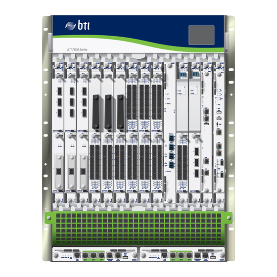
Juniper BTI7800 Series Hardware Overview And Installation Manual (228 pages)
Brand:
Juniper
| Category:
Network Hardware
| Size: 9.21 MB
Table of Contents
Table of Contents
3
About the Documentation
15
Documentation and Release Notes
15
Documentation Conventions
15
Table 1: Notice Icons
16
Table 2: Text and Syntax Conventions
16
Documentation Feedback
17
About the Documentation
17
Requesting Technical Support
18
Self-Help Online Tools and Resources
18
Creating a Service Request with JTAC
19
Chapter 1 BTI7800 Series Safety Information
21
Optical Precautions
21
Laser Safety
22
Laser Safety: Automatic Power Shutdown
22
Table 3: Timing of APSD and APR Operations
22
APSD on the 96-Channel Amplifier
23
BTI7800 Series Safety Information
23
Laser Safety: Automatic Power Reduction
24
APR on 96-Channel Amplifier Modules
25
Safety Rating and Label
25
BTI7800 Series Safety Information
25
Figure 1: Laser Safety Warning Label with Text
25
Figure 2: Laser Safety Warning Label Without Text
25
BTI7800 Series Laser Output Ports
26
Critical Site Warnings and Requirements
26
Table 4: Laser Output Ports
26
Table 5: Environmental Site Requirements
27
Critical Safety Warnings
28
NEBS Requirements
28
Chapter 2 BTI7800 Series Chassis
29
Chassis
29
Table 6: BTI7800 Chassis Types
29
BTI7814 Chassis
30
Table 7: BTI7814 Chassis Overview
30
BTI7800 Series Chassis
31
Figure 3: BTI7814 Chassis Front View
31
Figure 4: BTI7814 Chassis Rear View with 14-Slot Chassis DC Power Entry
31
BTI7814 Chassis Kits
32
Table 8: BTI7814 Major Common Equipment Components
32
Table 9: BTI7814 Kits
32
BTI7814 Chassis Specifications
33
Table 10: BTI7814 Chassis Specifications
33
BTI7802 Chassis
34
Figure 5: BTI7802 Chassis Front View
34
Table 11: BTI7802 Common Equipment Components
34
BTI7802 Chassis Kits
35
Table 12: BTI7802 Kits
35
BTI7802 Chassis Specifications
36
Table 13: BTI7802 Chassis Specifications
36
BTI7801 Chassis
37
Figure 6: BTI7801 Chassis Front View
37
BTI7801 Chassis Kits
38
Figure 7: BTI7801 Chassis Rear View
38
Table 14: BTI7801 Common Equipment Components
38
Table 15: BTI7801 Kits
38
BTI7801 Chassis Specifications
39
Power
39
Table 16: BTI7801 Chassis Specifications
39
BTI7814 Power
40
BTI7814 Power Distribution Plan
40
Bti7814 DC Pem
41
Table 17: BTI7814 Backplane DC Power Distribution
41
Figure 8: BTI7814 14-Slot Chassis DC Power Entry Module
42
BTI7814 DC PEM Specifications
43
Table 18: BTI7814 14-Slot Chassis DC Power Entry Module (BT8A78PEM3-DC)
43
Bti7814 Ac Pem
44
Figure 9: BTI7814 AC PEM Housing
45
Figure 10: BTI7814 AC PEM Rectifier
45
BTI7814 AC PEM Specifications
46
Table 19: BTI7814 AC Power Entry Module (BT8A78ACM1) Specifications
46
BTI7802 Power
48
BTI7802 Power Distribution Plan
48
Bti7802 DC Pem
48
BTI7802 DC PEM Specifications
49
Figure 11: BTI7802 1-Slot/2-Slot Chassis DC Power Entry Module
49
Table 20: BTI7802 1-Slot/2-Slot Chassis DC Power Entry Module (BT8A78PEM1-DC) Specifications
49
Bti7802 Ac Pem
50
BTI7802 AC PEM Specifications
51
Figure 12: BTI7802 1-Slot/2-Slot Chassis AC Power Entry Module
51
Table 21: BTI7802 1-Slot/2-Slot Chassis AC Power Entry Module
51
BTI7801 Power
52
BTI7801 Power Distribution Plan
52
Bti7801 DC Pem
52
Bti7801 Ac Pem
52
BTI7800 Series Component Power Consumption
53
Table 22: BTI7800 Series Component Power Consumption (at 40°C)
53
Cooling
55
BTI7814 Cooling System
55
BTI7814 FAN3 Specifications
56
Figure 13: BTI7814 Cooling System Air Flow
56
Table 23: 14-Slot Chassis Front Cooling Module (BT8A78FAN3)
56
BTI7814 Booster Fans
57
BTI7814 Booster Fan Specifications
58
BTI7802 Cooling System
58
Figure 14: BTI7802 Cooling Module Location
58
Table 24: FAN9 Specifications
58
Figure 15: 2-Slot Chassis Cooling Module (BT8A78FAN2) Right and Left Side
59
Figure 16: BTI7802 Cooling System
59
BTI7802 FAN2 Specifications
60
BTI7801 Cooling System
60
Figure 17: BTI7802 Cooling System with Rear Exhaust Adapter
60
Table 25: 2-Slot Chassis Cooling Module (BT8A78FAN2) Specifications
60
Figure 18: 1-Slot Chassis Front Cooling Module (BT8A78FAN5)
61
BTI7801 FAN5 Specifications
62
Figure 19: BTI7801 Airflow
62
Table 26: 1-Slot Chassis Front Cooling Module (BT8A78FAN5)
62
BTI7801 FAN5 Management Ports and the ESL Module
63
BTI7801 ESL Specifications
64
Figure 20: Ethernet and Serial Link Module (BT8A78ESL1)
64
Table 27: Ethernet and Serial Link (BT8A78ESL1) Specifications
64
Chassis Alarm Panel (CAP)
65
Bti7814 Cap
65
Figure 21: BTI7814 Chassis Alarm Panel
65
BTI7814 CAP1 Specifications
66
Bti7802 Cap
66
Table 28: 14-Slot Chassis Alarm Panel (BT8A78CAP1) Specifications
66
BTI7802 CAP2 Specifications
67
Bti7801 Cap
67
Figure 22: BTI7802 Chassis Alarm Panel
67
Table 29: 2-Slot Chassis Alarm Panel (BT8A78CAP2) Specifications
67
Chapter 3 Unpacking the BTI7800 Series Shipment
69
Unpacking the Equipment
69
Verify Shipment Contents
70
Lifting and Moving the BTI7814 Chassis
70
Figure 23: Chassis Installation Kit
71
Figure 24: Chassis Support Frame
72
Figure 25: Chassis Lift Handles
72
Mounting the Support Frame
72
Moving the Chassis
72
Chapter 4 Installing the BTI7800 Series Chassis
75
Site Requirements
75
Table 30: Environmental Site Requirements
75
Chassis Installation Kits
76
Table 31: Chassis Installation Kit (BT8A7865)
76
Table 32: BTI7814 Chassis Crimp Lug Installation Kit (BT8A7867)
77
Table 33: Miscellaneous Kits and Accessories
77
Tools for Installation
78
Installing the BTI7802 Chassis Rear Exhaust Adapter
78
Figure 26: Rear Exhaust Adapter Kit (BT8A78REX)
80
Rack-Mounting the Chassis
84
Rack-Mounting the BTI7814 Chassis
84
Table 34: Rack-Mounting Considerations
84
Rack-Mounting the BTI7802 Chassis
86
Table 35: Rack-Mounting Considerations
86
Rack-Mounting the BTI7801 Chassis
87
Table 36: Rack-Mounting Considerations
87
Grounding the Chassis
89
Frame-Grounding a BTI7814 Chassis
89
Frame-Grounding a BTI7802 Chassis
90
Frame-Grounding a BTI7801 Chassis
92
Powering the Chassis
94
Powering the BTI7814 Chassis
94
Connecting the DC Power Feeds to a BTI7814 DC PEM
94
Figure 27: DC PEM Power Feed Connections
96
Connecting the AC Power Feeds to a BTI7814 AC PEM
97
Powering the BTI7802 Chassis
100
Installing and Cabling the BTI7802 DC PEM
101
Table 37: BTI7802 DC Power Cable Assembly (BT8A78PWR1)
102
Installing and Cabling the BTI7802 AC PEM
103
Powering the BTI7801 Chassis
105
Installing and Cabling the BTI7801 DC PEM
105
Installing and Cabling the BTI7801 AC PEM
105
Connecting the ESD Wrist Strap Cable
105
BTI7814 ESD Jack Locations
105
BTI7802 ESD Jack Location
106
BTI7801 ESD Jack Location
106
Chapter 5 BTI7800 Series Modules
107
List of Modules
107
Table 38: BTI7800 Series Management and Traffic Modules
107
Module Installation and Removal Guidelines
108
Chassis Management Module (CMM)
110
Figure 28: CMM Module
110
Table 39: CMM Ports
110
CMM1 Specifications
111
Figure 29: CMM Slot Locations on BTI7814
111
Figure 30: CMM Slot Locations on BTI7802
111
Figure 31: CMM Slot Location on BTI7801 (Rear View)
111
Table 40: Chassis Management Module 1 (BT8A78CMM1) Specifications
111
CMM1 Latches
113
Installing a CMM
113
Removing a CMM
114
Universal Forwarding Module (UFM)
115
Table 41: UFM Types
115
Table 42: UFM Specifications
116
UFM Latches
116
UFM Specifications
116
Figure 32: Top Latch - UFM3 and UFM6
117
Figure 33: Top Latch - UFM4
117
Figure 34: Bottom Latch - Ufms
117
Installing a UFM
117
Removing a UFM
119
Replacing a UFM4 with a UFM3
120
Table 43: Installation Rules
121
UFM6 Installation Rules
121
BTI Interface Card (BIC)
122
Sfp+ Bic
122
Figure 35: 12X SFP+ BTI Interface Card
123
Table 44: 12X SFP+ BIC (BT8A78SFP12G) Specifications
123
Cfp Bic
124
Figure 36: 1X CFP BTI Interface Card
124
Table 45: 1X CFP BIC (BT8A78CFP1G) Specifications
124
BIC Handles and Latches
125
Installing a BIC
125
Removing a BIC
126
Figure 37: BIC Extractor Tool
127
Replacing a BIC
128
Installing or Removing a BIC Filler Panel
128
Figure 38: BIC Filler Panel
129
BIC Leds
130
96-Channel Amplifier (AMP1)
130
Table 46: BIC Leds
130
Table 47: AMP1 Ports
130
AMP1 Specifications
131
Figure 39: 96-Channel Amplifier Module
131
Table 48: AMP1 (BT8A78AMP1) Specifications
131
AMP1 Latches
133
Installing an AMP1 Module
133
Removing an AMP1 Module
134
Wavelength Protection Switch (WPS4)
135
Figure 40: WPS4 Module
136
Figure 41: WPS4 Ports
136
Table 49: WPS4 (BT8A78WPS4) Specifications
137
WPS4 Specifications
137
Table 50: Wavelength Protection Group Specifications
138
WPS4 Latches
138
Figure 42: Top Latch 1 - WPS4
139
Figure 43: Top Latch 2 - WPS4
139
Figure 44: Bottom Latch - WPS4
139
Installing a WPS4
139
Removing a WPS4
141
96-Channel Fixed Mux/Demux (FMD96)
142
Figure 45: Front Panel
142
C-Band
143
Figure 46: Block Diagram
143
Monitoring Points
143
Osc
143
96-Channel Fixed Mux/Demux Specifications
144
Table 51: FMD96 (BT8A78MD03) Specifications
144
Installing a 96-Channel Fixed Mux/Demux (BT8A78MD03)
145
Figure 47: 23-Inch Bracket Mounting Positions
147
Figure 48: 21-Inch Bracket Mounting Positions
147
Figure 49: 19-Inch Bracket Mounting Positions
148
Figure 50: Attach the Ground Cable
149
Removing an FMD96
150
Figure 51: Remove the Lug
151
Service Module Leds
151
Table 52: Service Module LED Behavior
151
Port Leds
152
Table 53: Port Leds (Ufms and Bics)
152
Table 54: Port Leds (Ufms and Optical Modules)
152
Chapter 6 BTI7800 Series Transceiver Specifications
153
BTI7800 Transceivers
153
Table 55: BTI7800 Series Transceivers
153
BTI7800 SFP+ Transceiver Optical Specifications
155
Table 56: SFP+ 850Nm 200M Dual-Rate 10.3 and 10.5Gbps (BP3AD6SS)
155
Table 57: SFP+ 1310Nm 10Km Multi-Rate 9.9 to 11.1Gbps (BP3AM6MS)
156
Table 58: SFP+ DWDM Fixed 80Km Multi-Rate 9.9 to 11.1Gbps
157
Specifications
159
Table 59: Receiver Transmission Optical Performance Specifications: BP3AM6DL-XX XX=[01,40]
160
Table 60: SFP+ DWDM Tunable 80Km Multi-Rate 9.9 to 11.1Gbps (BP3AM6TL)
160
Table 61: Receiver Transmission Optical Performance Specifications
161
BTI7800 QSFP+ Transceiver Optical Specifications
162
Table 62: QSFP+ 4X10Gbase LR: QSFPP-4X10GE-LR (740-054050)
162
Table 63: QSFP+ 4X10G Ethernet/Otn LR: QSFPP-4X10GD-LR (740-058730)
164
Table 64: QSFP+ 4X10Gbase SR: QSFPP-4X10GE-SR (740-054053)
165
Table 65: QSFP+ 40GE SR4: QSFPP-40GBASE-SR4 (740-067443)
166
Table 66: QSFP+ 40GE LR4: QSFPP-40GBASE-LR4
167
BTI7800 QSFP28 Transceiver Optical Specifications
168
Table 67: QSFP28 100GE LR4: QSFP-100G-LR4-2 (740-074685)
168
Table 68: QSFP28 100GE Ethernet/Otn LR4: QSFP-100G-LR4-D (740-073859)
170
Table 69: QSFP28 100GE SR4: QSFP-100GBASE-SR4 (740-058734)
170
BTI7800 100-Gbps Transceiver Optical Specifications
171
Table 70: QSFP28 100GE AOC: JNP-100G-AOC-XX (740-06Xxxx)
171
Table 71: CFP 100GBASE-SR10 100M: BP3AMASS
171
Table 72: CFP 100GBASE-LR4 10Km: BP3AMDLI
172
Table 73: 100G Coherent CFP-M05: CFP-100GBASE-CHRT
173
Table 74: 100G Coherent CFP: BP3AMCTL
174
Table 75: 100G Coherent MSA XCVR on UFM4
175
BTI7800 400-Gbps Transceiver Optical Specifications
176
Table 76: 400G Coherent MSA XCVR (2 X 200-Gbps) on UFM6
176
Installation Rules for the 100G Coherent CFP
177
Cleaning Transceivers
177
Table 77: Installation Rules for the 100G Coherent CFP in a BTI7814 Chassis
177
Chapter 7 BTI7800 Series Field Replaceable Units (Frus)
179
BTI7814 Field-Replaceable Units (Frus)
179
Replacing the BTI7814 DC PEM
180
Replacing the BTI7814 AC PEM
182
Replacing the Fuses on a BTI7814 AC PEM
185
Replacing the BTI7814 CAP
187
Replacing a BTI7814 FAN3
188
Replacing a BTI7814 Booster Fan
189
Performing a First Time Installation of the BTI7814 Booster Fans
190
Replacing a BTI7814 Air Filter
191
BTI7802 Field-Replaceable Units (Frus)
193
Replacing the BTI7802 PEM
193
Replacing the BTI7802 CAP
195
Replacing the BTI7802 FAN2
195
Replacing a BTI7802 Air Filter
197
BTI7801 Field-Replaceable Units (Frus)
199
Replacing the BTI7801 PEM
200
Replacing the BTI7801 FAN5
200
Replacing the BTI7801 ESL
201
Chapter 8 AC Rectifier (External)
203
AC Rectifier
203
Figure 52: Rectifier Shelf: Rear View
203
Table 78: Rectifier Kits
204
Installing the AC Rectifier
205
Table 79: Rectifier Shelf Rack Support
205
Chapter 9 Optical Protection Switch (OPS)
211
OPS Overview
211
OPS Equipment
212
Table 80: Optical Protection Switch Kit - Dual Switch Card (BT7A39AS)
212
Table 81: AC Power and Power Cables
212
OPS Specifications
213
Table 82: OPS Specifications
213
OPS AC Power Unit Specifications
214
Table 83: OPS AC Power Unit (BT7A39AE) Specifications
214
Chapter 10 Appendix
215
FIT Rates
215
Table 84: BTI7801 FIT Rates
215
Table 85: BTI7802 FIT Rates
215
Table 86: BTI7814 FIT Rates
216
Table 87: BTI7800 Series Module and BIC FIT Rates and MTBF
216
Table 88: BTI7800 Series Transceiver FIT Rates and MTBF
217
CAP Telco Alarm Connector Pin Assignments
218
Table 89: Optical Protection Switch (OPS) FIT Rates and MTBF
218
Table 90: CAP Telco Alarm Connector Pin Assignments
218
DWDM 50-Ghz Wavelength Plan
219
Table 91: DWDM Wavelength Plan (50-Ghz Spacing)
219
Maintaining Fiber-Optic Connectors
223
Inspecting Fiber-Optic Connectors
223
Cleaning Fiber-Optic Connectors
224
Fiber Breakout
225
Fiber Breakout for UFM6 QSFP+ Ports
225
Gigalight SMF Elite MTP (Angled) LC/UPC 1X8F to MTP Minicassette Specifications
226
Figure 53: Gigalight Cassette
226
Table 92: Gigalight SMF Elite MTP (Angled) LC/UPC 1X8F to MTP Minicassette
226
Gigalight 1U Gigac Rack Specifications
227
Fiber Breakout Components
227
Table 93: Gigalight 1U Gigac Rack Specifications
227
Advertisement
Advertisement
Related Products
Juniper BTI7814
Juniper BTI7802
Juniper BTI7801
Juniper BT8A78CH14
Juniper BT8A78CH2-I02
Juniper BT8A78CH1
Juniper BT11
Juniper BX7000
Juniper SYSTEM BASICS - CONFIGURATION GUIDE V 11.1.X
Juniper BGP
Juniper Categories
Network Router
Switch
Gateway
Software
Network Hardware
More Juniper Manuals
Login
Sign In
OR
Sign in with Facebook
Sign in with Google
Upload manual
Upload from disk
Upload from URL