Table of Contents
Advertisement
Quick Links
Advertisement
Table of Contents

Subscribe to Our Youtube Channel
Related Manuals for Xylem Goulds AquaBoost VS


Summary of Contents for Xylem Goulds AquaBoost VS
- Page 1 INSTRUCTION MANUAL 10-001-251 Rev 7 Variable Speed AquaBoost VS Pumping Packages...
-
Page 3: Table Of Contents
Table of Contents Table of Contents 1 Introduction and Safety......................3 1.1 Introduction.......................... 3 1.2 Safety............................. 3 1.2.1 Safety terminology and symbols.................3 1.2.2 Protecting the environment..................4 1.3 User safety..........................4 1.3.1 Wash the skin and eyes....................5 2 Transportation and Storage...................... 6 2.1 Examine the delivery...................... - Page 4 Table of Contents 7.1.3 The pumps run but do not build desired pressure..........27 7.1.4 The pump station experiences excessive vibration..........28 7.1.5 The pump station does not shut down and no water is used....... 28 7.1.6 The pump station cycles or hunts erratically............29 8 Other Relevant Documentation or Manuals.................
-
Page 5: Introduction And Safety
This includes any modification to the equipment or use of parts not provided by Xylem. If there is a question regarding the intended use of the equipment, please contact a Xylem representative before proceeding. -
Page 6: Protecting The Environment
• Clean-up of spills Exceptional sites CAUTION: Radiation Hazard Do NOT send the product to Xylem if it has been exposed to nuclear radiation, unless Xylem has been informed and appropriate actions have been agreed upon. Recycling guidelines Always follow local laws and regulations regarding recycling. -
Page 7: Wash The Skin And Eyes
1 Introduction and Safety • Hard hat • Safety goggles, preferably with side shields • Protective shoes • Protective gloves • Gas mask • Hearing protection • First-aid kit • Safety devices NOTICE: Never operate a unit unless safety devices are installed. Also see specific information about safety devices in other chapters of this manual. -
Page 8: Transportation And Storage
2 Transportation and Storage 2 Transportation and Storage 2.1 Examine the delivery 2.1.1 Examine the package 1. Examine the package for damaged or missing items upon delivery. 2. Record any damaged or missing items on the receipt and freight bill. 3. - Page 9 2 Transportation and Storage Treat bearings and machined surfaces so that they are well preserved. Refer to the drive unit and coupling manufacturers for their long-term storage procedures. For questions about possible long-term storage treatment services, please contact your local sales and service representative. AquaBoost VS Pumping Packages INSTRUCTION MANUAL...
-
Page 10: Product Description
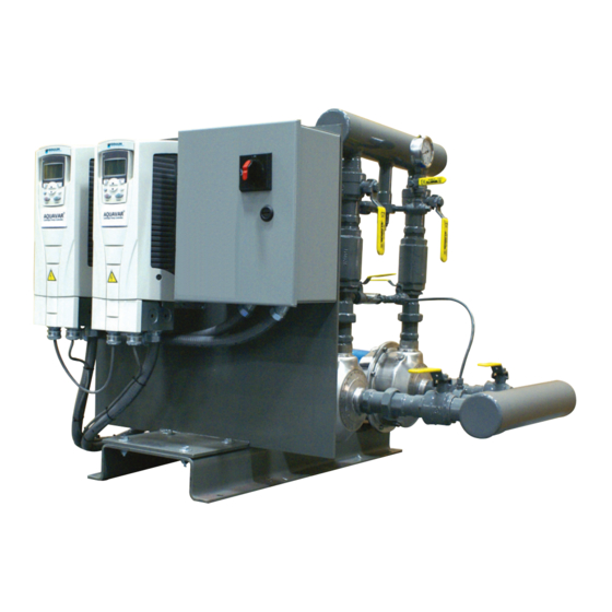
3 Product Description 3 Product Description 3.1 General description AquaBoost VS pumping package The AquaBoost Variable Speed pumping package can precisely match the pump discharge pressure to the system pressure by varying the speed of the pump. This is accomplished by using the variable-speed controllers such as the AquaBoost II and Aquavar CPC. -
Page 11: Nameplate Information
3 Product Description This variable-speed configuration uses the Aquavar CPC controller (for 3 & 5 HP 208-230/1, and 1.5-to-5 HP 3 PH power supply). 1. Pump: NPE with TEFC motor 2. Aquavar CPC controller 3. Transducer assembly 4. Safety Switch 5. - Page 12 3 Product Description • Model • Size • Serial number • Item numbers of the required parts Model number Serial number Voltage SCCR Phase Max. HP Nameplate field Explanation Model number The model number of the pump station Serial number The serial number of the pump station Voltage Input voltage required for the pump station...
- Page 13 3 Product Description Electrical ratings at startup Current Voltage Phase AquaBoost VS Pumping Packages INSTRUCTION MANUAL...
-
Page 14: Installation
4 Installation 4 Installation 4.1 Field connections Review the field piping diagrams and wiring diagrams before you install and operate the unit. Electrical precautions WARNING: Electrical shock hazard. The electrical supply must match the control panel nameplate specification. Incorrect voltage can cause a fire, which damages the electrical components and voids the warranty. -
Page 15: Field Piping Diagrams
4 Installation Overload protection for variable-speed units Variable-speed units have a single-point power panel with fuses for protection against voltage spikes. In addition, the controllers have inherent features that protect the unit against: • short circuit • undervoltage • overload •... - Page 16 4 Installation AquaBoost VS duplex Typical field piping arrangement for the AquaBoost Variable Speed duplex pumping package. 1. 1/4 in. tap on the suction manifold for low-suction pressure switch 2. Optional tank 3. Discharge gauge 4. Vibration eliminator 5. Anchor the pipe securely if vibration eliminators are used. 6.
-
Page 17: Wiring Diagrams
4 Installation 4.1.2 Wiring diagrams AquaBoost VS – Aquavar CPC controls AquaBoost VS Pumping Packages INSTRUCTION MANUAL... -
Page 18: Ground (Earth) Connections
4 Installation AquaBoost VS – ABII controls 4.2 ground (earth) connections WARNING: Electrical shock hazard. Conduit grounds are not adequate. You must attach a separate ground (earth) wire to the ground (earth) lug provided in the enclosure in order to avoid potential safety hazards. -
Page 19: Pump Package Location Guidelines
4 Installation A grounding terminal is provided for a dedicated ground (earth) wire connection. You must follow all provisions of the National Electrical Code and local codes. 4.3 Pump package location guidelines WARNING: Assembled units and their components are heavy. Failure to properly lift and support this equipment can result in serious physical injury and/or equipment damage. -
Page 20: Connect The Optional Storage Tank
4 Installation 4.6 Connect the optional storage tank 1. If the unit is a simplex configuration, then install the tank to the top connection of the discharge cross as shown: 1. Storage tank 2. Discharge gauge 2. If the unit is a duplex configuration, then connect the tank to the discharge manifold as shown: 1. -
Page 21: Piping Checklist
4 Installation 1. 1/4 in. inlet tap on check valve 2. If the unit is a duplex configuration, then install the low-suction pressure switch piped to the 1/4 in. tap on the suction manifold as shown: 1. 1/4 in. inlet tap on check valve 4.8 Piping checklist WARNING: •... - Page 22 4 Installation Check Explanation/comment Checked Check that a three-valve bypass has been installed This is a recommended field option. between the suction and discharge connections. Check that the piping to which optional vibration This is necessary for maximum effectiveness. eliminators are connected is properly anchored to the floor.
-
Page 23: Commissioning, Startup, Operation, And Shutdown
5 Commissioning, Startup, Operation, and Shutdown 5 Commissioning, Startup, Operation, and Shutdown 5.1 Preparation for startup DANGER: Electrical hazard sufficient to kill. Always disconnect and lock out the power before you service the unit. WARNING: • Failure to follow these precautions before you start the unit will lead to serious personal injury and equipment failure. -
Page 24: Final Adjustments
5 Commissioning, Startup, Operation, and Shutdown Final piping checklist Check Checked Check that the bypass valve is closed, if used. Check that the piping is properly supported. This prevents strain on the unit. Electrical wiring and control checklist WARNING: • Electrical shock hazard. Conduit grounds are not adequate. You must attach a separate ground (earth) wire to the ground (earth) lug provided in the enclosure in order to avoid potential safety hazards. -
Page 25: Pump Package Operation Description
5 Commissioning, Startup, Operation, and Shutdown The screw to the left and towards the front sets the cut-in point. Turn this screw until the proper cut-in pressure is obtained. 1. The silver adjusting screw on the left front is for cut-in adjustment. 2. - Page 26 5 Commissioning, Startup, Operation, and Shutdown Condition Description The system pressure falls below the set point. The pump starts automatically and pump speed continues to ramp up until the system pressure satisfies the set point. The system pressure rises above the set point. The pump automatically reduces speed until the system pressure reaches the set point, provided the minimum run timer has expired.
-
Page 27: Maintenance
6 Maintenance 6 Maintenance 6.1 Precautions DANGER: Electrical hazard sufficient to kill. Always disconnect and lock out the power before you service the unit. WARNING: • This manual clearly identifies accepted methods for disassembling units. These methods must be adhered to. Trapped liquid can rapidly expand and result in a violent explosion and injury. -
Page 28: Troubleshooting
7 Troubleshooting 7 Troubleshooting 7.1 Pump station troubleshooting DANGER: • Personal injury hazard. Troubleshooting a live control panel exposes personnel to hazardous voltages. Electrical troubleshooting must be done by a qualified electrician. Failure to follow these instructions will result in serious personal injury, death, and/or property damage. -
Page 29: The Pumps Run But Do Not Build Desired Pressure
7 Troubleshooting Cause Remedy The impeller is bound. Check to see if you can turn the pump by hand. Check for a bound impeller. A pressure transducer is faulty. Replace faulty pressure transducers. Motor wiring is loose. Make sure that motor wiring is securely connected. Motor windings have lost insulation strength. -
Page 30: The Pump Station Experiences Excessive Vibration
7 Troubleshooting Cause Remedy The inlet pressure does not match the project Check to see if the inlet pressure matches the project specifications. specifications. Variations in inlet pressure can have detrimental effects on performance. A pipe is broken. Check for broken pipes. The transducer isolation valves are closed. -
Page 31: The Pump Station Cycles Or Hunts Erratically
7 Troubleshooting Cause Remedy There are leaks or broken pipes. Check for broken pipes or leaks. Does the system pressure decrease if the pump station is turned off? The diaphragm tank is faulty. Check for a properly installed diaphragm tank. Has the tank failed? Has the tank been charged to the proper operating pressure before installation? (~10 psi below the desired set point) -
Page 32: Other Relevant Documentation Or Manuals
8 Other Relevant Documentation or Manuals 8 Other Relevant Documentation or Manuals 8.1 Manuals for AquaBoost components Further information pertaining to the installation, operation, and maintenance of your AquaBoost Pumping System can be found in the IOMs provided for the associated equipment: Equipment Manual... -
Page 33: Product Warranty
9 Product warranty 9 Product warranty Commercial warranty Warranty. For goods sold to commercial buyers, Seller warrants the goods sold to Buyer hereunder (with the exception of membranes, seals, gaskets, elastomer materials, coatings and other "wear parts" or consumables all of which are not warranted except as otherwise provided in the quotation or sales form) will be (i) be built in accordance with the specifications referred to in the quotation or sales form, if such specifications are expressly made a part of this Agreement, and (ii) free from defects in material and... - Page 34 9 Product warranty Limited consumer warranty Warranty. For goods sold for personal, family or household purposes, Seller warrants the goods purchased hereunder (with the exception of membranes, seals, gaskets, elastomer materials, coatings and other "wear parts" or consumables all of which are not warranted except as otherwise provided in the quotation or sales form) will be free from defects in material and workmanship for a period of one (1) year from the date of installation or eighteen (18) months from the product date code, whichever shall occur first, unless a...
- Page 35 9 Product warranty To make a warranty claim, check first with the dealer from whom you purchased the product or visit www.xyleminc.com for the name and location of the nearest dealer providing warranty service. AquaBoost VS Pumping Packages INSTRUCTION MANUAL...
- Page 36 For more information on how Xylem can help you, go to www.xylem.com Xylem Inc. Visit our Web site for the latest version of this document and more information 2881 East Bayard Street Ext., Suite A...
Need help?
Do you have a question about the Goulds AquaBoost VS and is the answer not in the manual?
Questions and answers