
Subscribe to Our Youtube Channel
Related Manuals for WPI MICRO-ePUMP


Summary of Contents for WPI MICRO-ePUMP
- Page 1 WORLD PRECISION INSTRUMENTS INSTRUCTION MANUAL MICRO-ePUMP Microinjector Serial No._____________________ www.wpiinc.com 012220...
-
Page 3: Table Of Contents
MICRO-ePUMP CONTENTS ABOUT THIS MANUAL ........................1 INTRODUCTION ..........................1 Features............................2 Benefits ............................2 Applications ..........................2 Notes and Warnings ......................... 3 Parts List ............................3 Unpacking ........................... 3 INSTRUMENT DESCRIPTION ......................4 Front Panel ..........................4 Rear Panel ........................... 5 Foot Switch .......................... - Page 4 World Precision Instruments...
-
Page 5: About This Manual
Designed to simplify intracellular injection and a variety of other micro in jec tion tasks, the MICRO-ePUMP uses carefully regulated air pres sure for injecting cells with fluid. Injected volumes range from picoliters to nanoliters. The port supplies positive pressure for high-pressure ejection. -
Page 6: Features
The MICRO-ePUMP is designed to inject very small quantities of fluids, such as drugs, into cells or small organelles. Pressure injection is an especially useful alternative to electroionophoresis, since it does not mandate the use of charged ions. Two different positive pressures may be applied–one for ejection at high pressure and a second,... -
Page 7: Notes And Warnings
Concealed damage should be reported at once to the carrier and an inspection requested. Please read the section entitled “Claims and Returns” on page 27 of this manual. Please contact WPI Customer Service if any parts are missing at (941) 371-1003 or customerservice@wpiinc.com. -
Page 8: Instrument Description
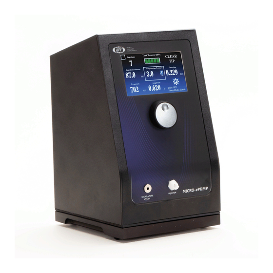
MICRO-ePORE™ Interface Cable Port Injector Port Fig. 2—The major features of the MICRO-ePUMP are labeled in this diagram. Touch Screen Interface – The responsive panel allows for intuitive control. Touch the injection counter to reset it, the tank pressure gauge to refill the tank, Clear Tip to blow a blast of air through the pipette tip, a parameter to modify it using the knob, or the settings area to adjust the settings. -
Page 9: Rear Panel
Power Supply Connection Fig. 4—The foot switch connection, power supply connection and power switch are located on the back panel of the MICRO-ePUMP. Foot Switch Connection – Plug the connector from the foot switch into the connection port marked with the foot switch icon. -
Page 10: Foot Switch
Protocol Loaded – The number in the box in the upper left corner indicates the protocol with stored parameters that is loaded. You can store and recall up to three of your most used protocols in the MICRO-ePUMP memory. If the box is empty, no protocol is loaded. -
Page 11: Setting Menu
Injection Time – Touch the parameter and rotate the knob to adjust the length of each injection. MICRO-ePORE™ Controller Frequency – The WPI MICRO-ePORE™ Pinpoint Cell Penetrator delivers a highly localized voltage signal to a targeted injection site to facilitate penetration with minimal trauma. The researcher determines the amplitude and frequency of the signal that best suits the application. -
Page 12: Setup
Silent check box. Select the Tone checkbox to enable the tones. Save/Load Protocols – The MICRO-ePUMP can store your three favorite parameter sets (protocols). On the main screen set the parameters as desired. Then press one of the Save buttons. - Page 13 MICRO-ePUMP Fig. 8—(Left) The power up screen shows the software revision on your MICRO-ePUMP. Fig. 9—As the self-test runs through the programmed diagnostic sequence, the display shows the results. Press the touchscreen to access the main screen. By default, the injection port is disabled.
- Page 14 Settings menu and touch the Port ON button to set it to Port OFF. Align the easy-connect Injector connector with the injector port on the front of the MICRO-ePUMP, slide the connector securely into the port and attach it with a slight clockwise twist.
- Page 15 MICRO-ePUMP Fig. 15—The Microelectrode Interface Cable has two connectors, one for the reference electrode and one for the microelectrode holder. • The red pin connects to the 2 mm socket on the microelectrode holder. Insert the red pin into the socket on the microelectrode holder.
-
Page 16: Operating Instructions
A box appears around the parameter to highlight it. Adjust the parameter by turning the knob. To change the dial adjustment speed, press the knob on the front of the MICRO-ePUMP. The snail changes the display in 0.01 increments, and the running man changes it in increments of 0.1. - Page 17 MICRO-ePUMP Changing the MICRO-ePORE™ Parameters When the MICRO-ePORE™ is disabled, the home screen does not show the MICRO-ePORE™ parameters in the bottom half of the screen. To enable the MICRO-ePORE™, touch the Settings area of the main screen to go to Settings menu.
- Page 18 • MICRO-ePORE™ status (Off or On) • MICRO-ePUMP mode (Manual or Timed) Fig. 27—(Left) The Setting area is located in the bottom right corner of the main screen. Fig. 28—(Right) Touch the Setting area to display the Settings menu. To modify these settings, press the Settings section on the touchscreen.
-
Page 19: Saving A Protocol
Press the Settings section on the touchscreen to access the Settings menu. Fig. 30—The Settings menu lets you save a protocol or load a saved protocol. To bring up a saved protocol with the MICRO-ePUMP parameters, press the LOAD 1, LOAD2 or LOAD3 button. The unit loads the saved parameters of Protocol 1, Protocol 2 or Protocol 3, depending on which LOAD button you chose. -
Page 20: Changing The Pipette
Settings menu and press the Port OFF button to enable the Injection Port. TECHNIQUES IN MICROINJECTION The MICRO-ePUMP was designed for demanding tasks like the microinjection of fluid into cells. In this section, we will look at several important things to keep in mind when working with the MICRO-ePUMP. - Page 21 MICRO-ePUMP dye is dissolved in the injection fluid. The capillary effect may be observed with the color change at the tip of the pipette. When the fluid flows into the pipette, the color of the tip becomes lighter. If the compensation pressure is higher than the capillary pressure, the fluid oozes out of the pipette.
-
Page 22: Manufacturing Micropipettes
Manufacturing Micropipettes Pulling suitable micropipettes is one of the biggest obstacles to taking full advantage of the MICRO-ePUMP. Both care and steady hands are required. The volume of fluid ejected is markedly dependent on the micropipette tip size. When using micron-sized tips a reduction in tip-size of a few percent may give an order of magnitude difference in the flow rate. -
Page 23: Calibrating Rate Using A Known Volume
From this we can calculate the rate of injection. For example, if the volume in 1 mm of glass with 0.58 µm ID (WPI #1B100) is 264 nL, and it takes 30 seconds to inject that volume, then the flow for 1 second is 264 nL/30 s or 8.8 nL/second, and a 1 nL volume then takes 0.113 seconds to inject. -
Page 24: Multibarrel Microinjection
The A drop of hot glue kits include a five-port manifold which provides a secure, leak-free seal. allows use of a single MICRO-ePUMP to drive up to six micropipette barrels independently. Fig. 35—PolyFil multibarrel micropipette coupling kit... -
Page 25: Maintenance
MICRO-ePUMP MAINTENANCE The MICRO-ePUMP has been designed to yield reliable performance. However, some laboratory conditions may require occasional replacement of the pressure filters. If this is necessary, return the instrument to the factory. If the unit displays a warning indicating that the pump needs service, please return it to the factory. -
Page 26: Troubleshooting
On power up the MICRO-ePUMP performs a diagnostic self-test. If there is a failure during the self-test, an error code displays and the unit stops the sequence. It will not progress into the operational mode unless it is powered off and then on, and the self- test completes without error. -
Page 27: Specifications
MICRO-ePUMP SPECIFICATIONS This unit conforms to the following specifications: PRESSURE Time Interval 0.001 - 2.000 s Time Increment 0.001 s Injection Pressure Range, Controlled 0.07 - 87.0 PSI (5 - 6000 hPa) Injection Pressure Increment 0.1 PSI (0.1 kPa) Injection Pressure, Uncontrolled... -
Page 28: Appendix A: Droplet Volume
APPENDIX A: DROPLET VOLUME Use the chart below to gauge the volume of a droplet and the table to determine the volume a micropipette can hold. 1 cm 215 µm 1 mL = 1.24 cm 10 nL = 267 µm 4.64 mm 100 µm 100 µL =... -
Page 29: Bibliography
MICRO-ePUMP BIBLIOGRAPHY R.E. McCaman, D.G. McKenna and J.K. Ono, glass surface: Choice of reagent and effect of A Pressure System for Intracellular and experimental parameters on hydrophobicity , Extracellular Ejections of Picoliter Volumes , Helv. Chim. Acta 65 (6) 1752-1759 (1982) Brain Research 136 141-147 (1977) Capecchi, M.R., High efficiency transformation... -
Page 30: Index
DECLARATION OF CONFORMITY World Precision Instruments... -
Page 31: Warranty
WPI shall not be liable for any damage to data or property that may be caused directly or indirectly by use of this product. - Page 32 175 Sarasota Center Blvd., Sarasota FL 34240-9258 Tel: 941-371-1003 • Fax: 941-377-5428 • E-mail: sales@wpiinc.com 1 Hunting Gate, Hitchin, Hertfordshire SG4 0TJ Tel: 44 (0)1462 424700 • Fax: 44 (0)1462 424701 • E-mail: wpiuk@wpi-europe.com Germany Pfingstweide 16, D-61169 Friedberg (Hessen), Germany Tel: +49 (0)6031 67708-0 •...
Need help?
Do you have a question about the MICRO-ePUMP and is the answer not in the manual?
Questions and answers