
Subscribe to Our Youtube Channel
Related Manuals for WPI M3301


Summary of Contents for WPI M3301
- Page 1 Micromanipulators Care and Maintenance INSTRUCTION SHEET Serial No._____________________ 052815 World Precision Instruments...
- Page 2 OTHER POPULAR WPI PRODUCTS High intensity source for Bifurcated fiber optic Light Guide 500186 illumination available separately The Z-LITE Fiber Optic Il lu mi na tor provides reli- able, un in ter rupt ed high- intensity light for micro- scopes. Z-LITE allows...
-
Page 3: Table Of Contents
Adjusting the Z Axis Drift ......................6 ACCESSORIES............................8 Manipulators ............................ 8 Optional Accessories ........................8 SPECIFICATIONS ........................... 8 KITE ..............................8 M3301............................... 9 MD4R ..............................9 MMJ ..............................9 DC3001............................. 9 0.2mm/s ............................9 0.2mm/s ............................9 0.2mm/s ............................9 WARRANTY ............................11... - Page 4 World Precision Instruments...
-
Page 5: About This Manual
Micromanipulator Care Guide ABOUT THIS MANUAL The following symbols are used in this guide: This symbol indicates a CAUTION. Cautions warn against actions that can cause damage to equipment. Please read these carefully. This symbol indicates a WARNING. Warnings alert you to actions that can cause personal injury or pose a physical threat. -
Page 6: Installing The Tilt Base
INSTALLING THE TILT BASE Fig. 1—(Left) M3 Tilting Base. Fig. 2— (Right) The M3301 is installed on an M3 Tilting Base with an optional 5 lb. weight (WPI# 5464). To install the M3 Tilting Base, remove the ring clamp by removing the two screws with the Allen wrench provided. -
Page 7: Adjusting The X Coarse Axis Drift
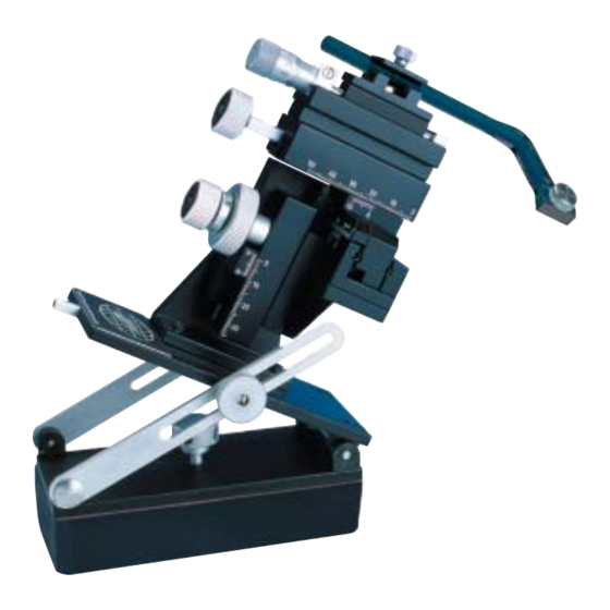
Y-Axis Coarse Adjustment Knob Adjustment Ring Fig. 3— The adjustment controls are labeled on an M3301 micromanipulator. Adjusting the X Coarse Axis Drift The fi rst step is to rotate the X-Axis Coarse Adjustment knob clockwise until the x-axis reaches the end of its travel in the fully extended position as indicated by the black arrow in Fig. - Page 8 If you are right-handed, hold the pliers in your left hand. With your right hand insert the special tool (WPI# 502105) (Fig. 6) into the black slot on the end of the knob. Prevent the silver knob from turning, and rotate the tool counter-clockwise to unscrew the black locking nut (Fig.
- Page 9 Micromanipulator Care Guide axis securely while adjusting the silver knob (clockwise to increase tension) with your right hand. At some point you will feel the resistance of the knob increase as it begins to compress against the spring steel and nylon friction components. Adjustment is somewhat arbitrary.
-
Page 10: Adjusting The Y-Axis Drift
Adjusting the Y-Axis Drift The adjustment of the Y-axis tension is performed with essentially the same techniques as that described for the X coarse axis. The Y-axis is controlled by the Y-Axis Coarse Adjustment knob shown in Fig. 3. If the manipulator is operated in standard position (with the electrode clamp located above the manipulator body as shown in Fig. - Page 11 Micromanipulator Care Guide Fig. 10— The fl at blade of the screwdriver should be positioned perpendicular to the adjustment ring to make the ring easier to rotate. The perpendicular position of the screwdriver creates a leverage point for using the screwdriver to amplify the force applied to turn the ring.
-
Page 12: Accessories
KITE-M3-R (or L) Kite, right (or left) + Tilting Base Combo M3301R (or L) Manual Manipulator, right (or left) M3301-M3-R (or L) Manual Manipulator, right (or left) with Tilting Base MD4R (or L) Double Holder Micromanipulator, right (or left) MD4-M3-R (or L) Double Holder Micromanipulato, right (or left) &... -
Page 13: M3301
Micromanipulator Care Guide M3301 TRAVEL RANGE RESOLUTION X-axis Fine 10mm 0.01mm X-axis 37mm 0.1mm Y-axis 20mm 0.1mm Z-axis 25mm 0.1mm SHIPPING WEIGHT 3 lbs (1.4 kg) MD4R TRAVEL RANGE RESOLUTION X-axis Fine 10mm 10μm X-axis 37mm 100μm Y-axis 20mm 100μmm... - Page 14 World Precision Instruments...
-
Page 15: Warranty
WPI shall not be liable for any damage to data or property that may be caused directly or indirectly by use of this product. - Page 16 International Trade Center, 175 Sarasota Center Blvd., Sarasota FL 34240-9258 Tel: 941-371-1003 • Fax: 941-377-5428 • E-mail: sales@wpiinc.com 1 Hunting Gate, Hitchin, Hertfordshire SG4 0TJ Tel: 44 (0)1462 424700 • Fax: 44 (0)1462 424701 • E-mail: wpiuk@wpi-europe.com Germany Zossener Str. 55, 10961 Berlin Tel: 030-6188845 •...
Need help?
Do you have a question about the M3301 and is the answer not in the manual?
Questions and answers