
Subscribe to Our Youtube Channel
Related Manuals for WPI NANOLITER2020


Summary of Contents for WPI NANOLITER2020
- Page 1 WORLD PRECISION INSTRUMENTS INSTRUCTION MANUAL NANOLITER2020 MICRO2T SMARTouch™ Controller-Based Nanoliter 2020 Injection Serial No._____________________ www.wpiinc.com 082020...
-
Page 3: Table Of Contents
Micropipette Filling Techniques ....................20 Back Filling ..........................20 Front Filling ..........................20 Typical Filling Technique ......................20 Installing Oil Back Filled Micropipettes in NANOLITER2020 Injector Head ...... 21 Front Filling Sample and Injecting Sample ................22 MAINTENANCE ............................24 Replacing O-Rings ........................... 24 Replacing the Wire Plunger ...................... - Page 4 NANOLITER2020 Injector ......................28 MICRO2T Controller ........................28 APPENDIX A: MICRO2T CONFIGURATIONS ..................29 Selecting System Options ......................29 Disabling Sound Feedback ....................29 Enabling Remote (Computer) Access .................. 29 Disabling Motors for Low Noise Recording ................ 30 Setting Screen Brightness ...................... 30 Resetting System Defaults ......................
-
Page 5: About This Manual
MICRO2T controller. INTRODUCTION The NANOLITER2020 Injector works on the principle of positive displacement. An internal micro-step motor precisely moves the metal (stainless steel) plunger (also referred to as the piston) which pushes the oil inside the micropipette, and the oil layer pushes the aqueous sample, dispensing specific nanoliter volumes ranging from 5-4500 nL at selectable delivery rates. -
Page 6: Notes And Warnings
Notes and Warnings CAUTION: Do NOT apply solvents or oils to any part of the NANOLITER2020. Do NOT wash or lubricate any parts of the system. CAUTION: The NANOLITER2020 Injector Head (3004704), MICRO2T controller, and other part are not autoclavable. Do not autoclave. -
Page 7: Unpacking
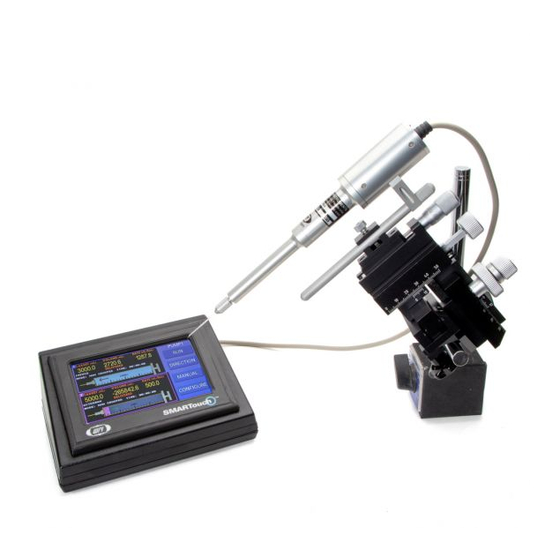
Concealed damage should be reported at once to the carrier and an inspection requested. Please read the section entitled “Claims and Returns” on page 39 of this manual. Please contact WPI Customer Service if any parts are missing at (941) 371-1003 or customerservice@wpiinc.com. - Page 8 Univerasal Adapter for NANOLITER Injector 300704 NANOLITER Injector M3301 Micromanipulator on a magnetic stand (Micromanipulator and stand are not included with the NANOLITER2020.) Fig. 2—NANOLITER 2020 System can be used on a micromanipulator which is NOT included with the NANOLITER2020.
-
Page 9: Power/Run Led Indicator On Nanoliter Injector Head
Fig. 4—The LED indicator on the NANOLITER2020 Injector Head indicates proper communication with the MICRO2T Controller. MICRO2T Description The MICRO2T is used to control one or two NANOLITER2020 or UMP3 pumps. Fig. 5—The MICRO2T touch screen controller shows the command screen. World Precision Instruments... -
Page 10: Pump Information Display Showing Two Pumps
Configuration Menu Pump Information Display Pump Information Display Showing Two Pumps 2-Channel Command Selected Pump Command Buttons Configuration Menu Pump Information Display Fig. 6—The Command screen provides pump information and has buttons to control the pumps. Selected Pump–Touch one of the pump data displays in the Pump Information Display area to select a pump. - Page 11 NANOLITER 2020/200704 • Direction toggles the direction of the selected pump between infuse and withdraw. When the direction button is pressed, the selected pump’s information display updates with the new direction of travel. A yellow arrow pointing toward the needle end of the syringe indicates infusion. A red arrow in the opposite direction indicates withdrawal.
-
Page 12: Back Panel Of Micro2T
Back Panel of MICRO2T The back of the MICRO2T has all the electrical connection ports and the power switch. USB Serial Connection Power Supply Port Output Connections (for UMP3 or Nanoliter 2010) 3.5mm Foot Switch Port Power Switch Fig. 9—The rear panel of the MICRO2T controller has the power switch and the connection ports for power, pumps, foot switch and computer control via USB. -
Page 13: Setting Up The System
The control box may be cleaned by wiping it with a clean, damp cloth. Setting up the Injector The NANOLITER2020 Injector Head by default is configured with a green front gasket and two o-rings. Follow steps 1 and 2 to replace the gaskets. -
Page 14: Replacing The Gaskets
See “Setting up the Injector” on page 9. Connecting the NANOLITER2020 Injector with the Controller Plug the NANOLITER2020 cable into one of the Output connection ports on the rear panel of the SMARTouch™ controller (Fig. 15). Make sure the marked arrow on the connector is facing upwards for proper pin alignment. - Page 15 (Fig. 17). Fig. 17—Connect the power cord to the power supply. If the foot switch (WPI# 13142, not included) is needed, plug it into the foot switch port on the rear panel of the MICRO2T controller (Fig. 9). Press the power button on the rear panel of the MICRO2T SMARTouch™ controller to power on the unit.
-
Page 16: Operating Instructions
OPERATING INSTRUCTIONS Setting Parameters NOTE: All parameters are stored in memory, even when the controller is powered off. Accessing the Configuration Screen Select the appropriate pump channel on the Command screen by tapping the desired channel on the display. Fig. 18—Channel 1 is selected, and PUMP1 is shown with a blue field behind it in the upper right corner of the display screen. -
Page 17: Defining Syringe Parameters
NANOLITER 2020/200704 Defining Syringe Parameters The syringe parameters are set on the Configuration screen for your selected pump. To access the Configuration screen, select a pump by tapping on the display from the Command screen. Then, click Configure for your selected pump. See “Accessing the Configuration Screen”... -
Page 18: Defining Pump Parameters
Press Enter to store the new value or press Back to return to the Configuration screen without saving any changes. TIP: If you enter an erroneous value, click Delete to clear it. Then, use the keypad to enter a new value. Defining Pump Parameters The pump parameters define how the selected pump responds. -
Page 19: Calibrating The Micro2T System Travel Limits
Non-Grouped–Non-grouped pumps operate independently. Calibrating the MICRO2T System Travel Limits The MICRO2T monitors the location of the NANOLITER2020 plunger. It is important to define the limits of travel before you begin using the pump. This keeps the pump from driving past the mechanical limits of the pump and avoids any jamming issues. When you install a pump on a new channel, you must set the stop positions so the controller will properly monitor the pump. -
Page 20: Setting End Stop In The Nanoliter Injector
CAUTION: IF YOU SUSPECT THAT THE PUMP HAS STALLED, CHECK THE END STOP CALIBRATION AGAIN. Set Syringe: This button is not used for the NANOLITER2020 Injector. Setting End Stop in the Nanoliter Injector Power on the MICRO2T unit. The splash screen appears. Touch the screen anywhere. - Page 21 Press anywhere in the PUMP1 display area to make PUMP1 the active pump. NOTE: Make sure the NANOLITER2020 is plugged into Port 1 of the MICRO2T controller. Fig. 26—To make a pump active, press anywhere in the PUMP Display Area on the Syringe Status screen.
- Page 22 (Fast and Slow). Withdraw Infuse Slow Fast Use the navigation buttons to set the position of the plunger at the base of the NANOLITER2020 collet. The plunger should extend 1-2 mm outside of the collet opening. World Precision Instruments...
- Page 23 NANOLITER 2020/200704 Withdraw plunger to this position Collet Plunger Glass Fig. 31—(Left) Use the four white navigation buttons to set the position of the plunger. Fig. 32—(Right) Using the navigation buttons, withdraw the plunger until you see it reach its withdrawn position at the base of the collet where the arrow is pointing in this image.
-
Page 24: Micropipette Filling Techniques
Front filling is achieved by creating a vacuum at the back end of the pipette that pulls the filling liquid into the micropipette. Once the micropipette is installed on the NANOLITER2020 Injector Head, it is possible to front fill. Front filling is advantageous for small volumes of expensive samples. -
Page 25: Installing Oil Back Filled Micropipettes In Nanoliter2020 Injector Head
Fig. 35—MicroFil is a thin flexible needle that lets you quickly back fill a micropipette. Install the back filled micropipette on to the NANOLITER2020 Injector – First unscrew the collet. Slide the blunt end of the micropipette through the tip of the collet. -
Page 26: Front Filling Sample And Injecting Sample
Micropipette does not come out when you pull gently. Fig. 38—Micropipette does not come out when you pull gently NOTE: THE NANOLITER2020 WILL NOT OPERATE PROPERLY WITHOUT BACKFILLING THE MICROPIPETTE. Front Filling Sample and Injecting Sample With the oil back filled micropipette installed onto the NANOLITER Injector Head, press the CONFIGURE button to access the Pump Configuration screen. - Page 27 >15 nL and discard the volume.) All subsequent injections will be accurate while the injector continues to run in the same direction (infuse/inject). NOTE: The MICRO2T Motor Drive Mode of Max Load is recommended for use with the NANOLITER2020 Injector. World Precision Instruments...
-
Page 28: Maintenance
After a period of time, you may observe some leakage around the seals. To correct this, replace the O-rings. Replacement O-rings are included with your NANOLITER2020. Additional O-rings (WPI #300746) may also be ordered. Fig. 44 shows the proper installation configurations. Correct orientation of the O-rings is critical for proper operation. -
Page 29: Replacing The Wire Plunger
NANOLITER 2020/200704 Replacing the Wire Plunger Verify that the plunger is in the home (retracted) position, just inside the collet. Do not try to retract it too much. Hold the motor housing with one hand while loosening the aluminum barrel. To remove it, unscrew it in a counter-clockwise direction with your other hand. -
Page 30: Cleaning Recommendations
Simply turn the cylinder (barrel) clockwise with gentle pressure to re-tighten it. Do NOT over-tighten it! Fig. 48—The NANOLITER2020 is reassembled. Cleaning Recommendations The injector can be cleaned by removing the collet, O-rings and spacers and wiping them with alcohol. -
Page 31: Troubleshooting
NOTE: If you have a problem/issue with that falls outside the definitions of this troubleshooting section, contact the WPI Technical Support team at (941) 371-1003 or technicalsupport@wpiinc.com. World Precision Instruments... -
Page 32: Specifications
SPECIFICATIONS NANOLITER2020 Injector This unit conforms to the following specifications: NANOLITER 2020 Plunger Outer Diameter ..............482 µm Plunger Movement for 100 nL Volume Dispense ........550 µm ± 55 µm Piston Movement per dispensed volume (nL) ............5.5 µm/nL Linear Travel Per Full Step ..................12.7 µm/step Minimum Volume (Injection) ..................... -
Page 33: Appendix A: Micro2T Configurations
NANOLITER 2020/200704 APPENDIX A: MICRO2T CONFIGURATIONS Selecting System Options The System Options screen gives you immediate access to basic parameters for your operations. To access the System Options screen: • Select System Options from the main menu, or • From the Pump Configuration screen, press Options. Fig. -
Page 34: Disabling Motors For Low Noise Recording
When you return to any other screen, the motors automatically re-enable themselves. To disable the drive motors on the NANOLITER2020 pumps, select the Low Noise Recording check box. When you press the Back button to return to the previous screen, a warning appears. -
Page 35: Resetting Limits After Power Failure
NANOLITER 2020/200704 Resetting Limits after Power Failure The MICRO2T records the location of all syringes when they stop. The information is recalled the next time the MICRO2T powers up. This allows the instrument to resume operation from the previous state without need to re-enter the syringe’s position. If the MICRO2T is powered down while a volume delivery is taking place, the location at the time where power is removed is not recorded. - Page 36 When you finish setting up the pump and syringe parameters, press Back to return to the Command screen. Fig. 54—Pump 2 is the Master pump, and Pump 1 is the slave in this example. Press Run to infuse the required volume of fluid for the injection or for multiple injections.
-
Page 37: Appendix B: Micro2T Computer Control
NANOLITER 2020/200704 APPENDIX B: MICRO2T COMPUTER CONTROL Serial commands are used to control the MICRO2T via the serial port of a computer using a free USB port. Serial Commands All commands are case sensitive. The settings for the serial port are 9600 baud rate, 8 data bits, 1 start bit and 1 stop bit. - Page 38 Command Syntax Notes Display syringe type Response: Type 8, 100.0uL, 60.0 Display direction type Response: Direction: Infuse (Direction: Withdraw) Display rate units Response: Rate Units: nL/min (Rate Units: nL/sec) Display run mode Response: Motor State: Stopped (Motor State: Running, Motor State: Paused) Pause script execution A#### #### is length of pause in seconds/100...
-
Page 39: Appendix C: Frequently Asked Questions
MICRO2T controller. Can I run the pump using a foot switch? Yes, you can use the 13142 Foot switch. This is not included in the NANOLITER2020 system and is sold separately. What do I do when glass micropipettes come off after attaching or I am unable to front fill a sample? Odorless and colorless mineral oil is used for back filling glass micropipettes. -
Page 40: Index
INDEX filling micropipette 20 plunger displacement 1 Symbols fire-polished glass 3 positive displacement 1 3563 2 firmware version 30 power failure 31 13142 26, 35 foot switch 8, 11, 35 power supply 11 14456 2 forceps 10 pulsations 14 300514 2 frequently asked questions 35 pump information display 6, 7 300703 2 front filling 20, 22, 35... - Page 41 NANOLITER 2020/200704 World Precision Instruments...
-
Page 42: Declaration Of Conformity
DECLARATION OF CONFORMITY World Precision Instruments... -
Page 43: Warranty
WPI shall not be liable for any damage to data or property that may be caused directly or indirectly by use of this product. - Page 44 175 Sarasota Center Blvd., Sarasota FL 34240-9258 Tel: 941-371-1003 • Fax: 941-377-5428 • E-mail: sales@wpiinc.com 1 Hunting Gate, Hitchin, Hertfordshire SG4 0TJ Tel: 44 (0)1462 424700 • Fax: 44 (0)1462 424701 • E-mail: wpiuk@wpi-europe.com Germany Pfingstweide 16, D-61169 Friedberg (Hessen), Germany Tel: +49 (0)6031 67708-0 •...
Need help?
Do you have a question about the NANOLITER2020 and is the answer not in the manual?
Questions and answers