Resol DeltaTherm PV Installation, Operation, Functions And Options, Troubleshooting
Power-to-heat controller
Hide thumbs
Also See for DeltaTherm PV:
- Manual for the specialised craftsman (28 pages) ,
- Manual (52 pages)
Table of Contents
Advertisement
Quick Links
DeltaTherm
Power-to-Heat controller
for the direct control of an
electric heater
Manual for the
specialised craftsman
Installation
Operation
Functions and options
Troubleshooting
The Internet portal for easy and secure access to
your system data – www.vbus.net
Thank you for buying this RESOL product.
Please read this manual carefully to get the best performance from this unit. Please keep this manual safe.
PV
®
Beginning with firmware version 1.03
en
Manual
www.resol.com
Advertisement
Table of Contents

Related Manuals for Resol DeltaTherm PV


Summary of Contents for Resol DeltaTherm PV
- Page 1 The Internet portal for easy and secure access to your system data – www.vbus.net Thank you for buying this RESOL product. Manual Please read this manual carefully to get the best performance from this unit. Please keep this manual safe.
- Page 2 Safety advice Information about the products Please pay attention to the following safety advice in order to avoid danger and Proper usage damage to people and property. The controller is designed for the direct control of an electric heater for using Danger of electric shock: excess current for heating a water store in compliance with the technical data •...
- Page 3 Disposal • Dispose of the packaging in an environmentally sound manner. • At the end of its working life, the product must not be disposed of as urban waste. Old appliances must be disposed of by an authorised body in an environmentally sound manner.
-
Page 4: Table Of Contents
DeltaTherm ® The DeltaTherm PV controller detects excess current, e.g. produced by PV ® Single-phase electromechanical electric immersion heaters up to 3 kW with an systems, calculates the energy available and redirects it to an electric heater. Thus, operating voltage of 230 V~ and a thermal cut-out are suitable. excess current can be directly converted into thermal energy and stored. -
Page 5: Deltatherm ® Pv
DeltaTherm ® Technical data sensor module (DeltaTherm E sensor) ® • Increase in self-consumption • Stepless control of an electric immersion heater Inputs: 3 current inputs and 3 voltage inputs for SW16 current sensors • Household current priority Power supply: 100 – 240 V~ (50 – 60 Hz) •... -
Page 6: System Overview
System overview Sensors Output Controller with power unit Energy meter Temperature store 1 / GND Out1 Electric Out 1 / N / ⏚ immersion optional 2 / GND heater optional 3 / GND Inverter 21 / 22 (optional) DIn1 Smart Remote 9 / 10 DIn2 Smart Remote... -
Page 7: Installation
Dimensions and minimum distances Installation Mounting WARNING! Electric shock! Upon opening the housing, live parts are exposed! Î Always disconnect the device from power supply before opening the housing! Note Strong electromagnetic fields can impair the function of the device. Î... - Page 8 105mm 105mm...
-
Page 9: Electrical Connection
Step-by-step installation: Electrical connection Damage through overheating! ATTENTION! Electric shock! WARNING! Commissioning the immersion heater in a system electrical- Upon opening the housing, live parts are exposed! ly connected, but not hydraulically filled can lead to damage Î Always disconnect the device from power supply caused by overheating! before opening the housing! Î... - Page 10 Sensor module Bus cable to the DeltaTherm PV (SM) ® Data communication / Bus The connection is to be carried out at the terminals marked SM (either polarity). The connection to the controller is to be carried out at the terminals marked SM (7 / 8).
- Page 11 Three-phase connection Single-phase connection Connect the current sensor and the conductor L1 of the sensor module di- Connect the current sensors and the conductors of the sensor module in rectly at the energy meter. The arrow indicated on the current sensor must phase directly at the energy meter.
- Page 12 Controller with power unit Din2 Bus cable to the Din1 E sensor DeltaTherm DeltaTherm ® ® IP20 Made in Germany 10 V IN 10 V REF VBus Power Supply 100 ... 240 F 16 A T16 A 50-60 Hz Din2 Din1 DeltaTherm ®...
-
Page 13: Microsd Card Slot Of The Controller
MicroSD card slot of the controller Connection of the electric heater The controller is equipped with a MicroSD card slot. Î Use a shielded cable with a cross section of 3 x 2.5 mm² and a maximum With a MicroSD card, the following functions can be carried out: length of 5 m for connecting the electric immersion heater. -
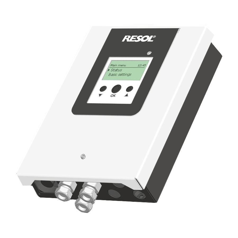
Page 14: Operation And Function Of The Controller
Operation and function of the controller To enter the previous menu, scroll upwards by pressing button or scroll downwards by pressing button until back is indicated. Buttons Press the centre button (OK). Operating control LED If the symbol ⏩ is shown behind a menu item, pressing the centre button (OK) will open a new submenu. - Page 15 Adjusting the timer When the Timer option is activated, a timer is in- dicated in which time frames for the function can be adjusted. In the Day selection channel, the days of the week are available individually and as frequently selected combinations.
- Page 16 Copying a time frame: Changing a time frame: In order to copy time frames already adjusted into an- In order to change a time frame, proceed as follows: other day / another combination, proceed as follows: Choose the day / the combination into which the time frames are to be copied and select Copy from.
-
Page 17: Commissioning
Resetting the timer: Commissioning In order to reset time frames adjusted for a certain day When the hydraulic system is filled and ready for operation, connect the controller or combination, proceed as follows: to the mains. The controller has to be connected to the sensor module by means of the bus (SM). The controller runs an initialisation phase in which the operating control LED glows red. - Page 18 8. Completing the commissioning menu: 1. Language: Lastly a security enquiry will appear. If the security en- Î Adjust the desired menu language. quiry is confirmed, the adjustments will be saved. In order to confirm the security enquiry, press the centre button (OK).
-
Page 19: Menu Structure
Menu structure Main menu Main menu Status Status Controller Controller Meas. / Balance values Variant Messages Optional functions Basic settings Controller In this menu, different menu areas can be selected. SD card Maximum temperature The following menus are available: Manual mode Hysteresis •... -
Page 20: Controller
4.5.1 Controller 4.5.2 Measured / Balance values In the Status / Meas. / Balance values menu, all current measurement values as In the Status / Controller menu, all current controller values (power values, tem- well as a range of balance values are displayed. peratures, etc.) are indicated. -
Page 21: Messages
4.5.3 Messages Smart Remote In the Status / Messages menu, error and warning messages are indicated. The Smart Remote function is used for remote access to the controller via a During normal operation, the message Everything OK is indicated. 4-state signal. A message consists of a short text about the fault condition. -
Page 22: Controller Menu
Controller menu Variant menu In this menu, all adjustments for the DeltaTherm ® PV can be made. In this menu, the characteristic curve for the power control is adjusted. The source The maximum temperature and the nominal power have already been adjusted for the power control of the electric immersion heater has already been adjusted during commissioning. -
Page 23: Optional Functions
Optional functions If the menu item Delete function is confirmed by pressing the right button (✓), a security enquiry appears. The left and the right button can be used for changing In this menu, optional functions can be selected and adjusted for the arrangement. between Yes and No. - Page 24 The internal backup heating function is used for operating the electric heating Opt. functions / Add new function / Inverter for backup heating with current from the mains. To do so, the power unit is switched Adjustment Adjustment range / selection Factory setting Description on.
-
Page 25: Basic Settings
4.10 Basic settings The controller is equipped with a MicroSD card slot for MicroSD memory cards. With a MicroSD card, the following functions can be carried out: • Logging measurement and balance values. After the transfer to a computer, the values can be opened and visualised, e.g. -
Page 26: Manual Mode
Loading controller adjustments Running firmware updates Î To load controller adjustments from a MicroSD card, select the menu item When a MicroSD card with a firmware update is inserted, the menu item Up- Load adjustments. date appears. The File selection window will appear. Î... -
Page 27: User Code
The following options are available: Troubleshooting Auto = Power unit is in automatic mode If a malfunction occurs, a message will appear on the display of the controller (see = Power unit is switched off page 21). 100 % = Power unit is switched on at 100 % The power of the modulating stage can be set to the manual mode in steps of 10 %. - Page 28 The operating control LED flashes red and an error is indicated in the status The error LED of the sensor module is flashing red. menu. Operating control LED of the controller is permanently red? Is the message !Sensor fault indicated in the Status / Messages menu? Is the message !Sensor module indicated in the Status / Messages menu? Is the message !Fan indicated in the Sensor fault.
- Page 29 Operating control LED is permanently red. The display is permanently off. Is the message !Sensor module indicated in the Status / Messages menu? Press the any button. Display illuminated? The error LED of the sensor module is flashing red? Check the power supply of the controller. Is it Controller has been in standby, everything OK disconnected?
-
Page 30: Accessories
Accessories Electric immersion heater For mounting into the store. DL3 Datalogger For visualisation via VBus.net, incl. SD card, mains adapter, network and VBus cable. ® DL2 Datalogger For visualisation via VBus.net, incl. SD card and network cable, mains adapter and VBus cable pre-connected. -
Page 31: Index
Index Adjusting the timer ......................15 Manual mode ........................26 Maximum temperature ...................... 22 Balance values ........................20 Measured values ........................20 Battery ............................. 6 MicroSD card ........................ 13, 25 Booster ..........................20 Mounting ..........................7 Commissioning menu ......................17 Nominal power........................ - Page 32 - they only represent outside the copyright requires the approval of RESOL – Elektronische Regelungen some examples. They can only be used at your own risk. No liability is assumed for GmbH.
Need help?
Do you have a question about the DeltaTherm PV and is the answer not in the manual?
Questions and answers