Advertisement
Available languages
Available languages
Quick Links
HIGHWAY
Brevettato - Patented
EP 2 642 028 A1
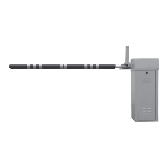
BARRIERA AUTOMATICA AD USO SUPER INTENSIVO PER PARCHEGGI E PASSAGGI AUTOSTRADALI
AUTOMATIC BARRIER FOR SUPER INTESIVE USE ON PARKINGS AND HIGHWAYS TOLL STATIONS
DESTRA
RIGHT
Operatore
Operator
HIGHWAY DX
HIGHWAY SX
SINISTRA
LEFT
Alimentazione
Lunghezza max asta
Power Supply
Max. boom lenght
230V/50-60Hz
2 ÷ 3 m
ITALIANO pag. 04 / ENGLISH page 17
Tempo di movimento
Operating time
min 1 s in apre
min 1,5 s in chiude
con rallentamenti attivati
min 1 s in opening
min 1,5 s in closing
with active slow speed in
approaching
Servizio
Codice
Service
Code
AA50600
100%
AA50605
Advertisement

Related Manuals for RIB Highway DX


Summary of Contents for RIB Highway DX
- Page 1 Codice Operator Power Supply Max. boom lenght Operating time Service Code min 1 s in apre HIGHWAY DX AA50600 min 1,5 s in chiude con rallentamenti attivati 230V/50-60Hz 2 ÷ 3 m 100% min 1 s in opening min 1,5 s in closing...
-
Page 2: Installation
2° - For the section and the type of the cables RIB advices to use a cable of H05RN-F type 2° - Per la sezione ed il tipo dei cavi la RIB consiglia di utilizzare un cavo di tipo H05RN-F... - Page 3 1. Sistema motorizzato di riaggancio asta 1. Motorized system to re-engage the boom 2. Motoriduttore ventilato con servizio 100% 2. Fan-cooled operator with service 100% 3. Molla bilanciamento asta 3.
-
Page 4: Caratteristiche Tecniche
LAYOUT IMPIANTO CARATTERISTICHE TECNICHE con bande catarifrangenti. - Freno elettronico in accostamento in apertura e chiusura. - Dotata di centrale PLC ed Inverter per mantenimento della posizione di chiusura e gestione - Motoriduttore reversibile ad uso intensivo utilizzato per movimentare aste lunghe fino a 3 m. del movimento dell’asta. - Page 5 HIGHWAY con asta in carbonio Misure in mm HIGHWAY con asta in alluminio Misure in mm...
- Page 6 INSTALLAZIONE HIGHWAY FISSAGGIO - Cementare la piastra di fissaggio (cod. ACG8110) nella posizione ritenuta ideale. - Aprire lo sportello utilizzando la chiave in dotazione (Fig. 1-2-3). - Procedere al fissaggio della HIGHWAY utilizzando i dadi, le rondelle in dotazione e una chiave esagonale n°...
- Page 7 TABELLA TARATURA MOLLE ASTA TIPO DI MOLLA MISURA M (Fig. 14) 2 m Carbonio Cod. ACG8620 323 mm 2,5 m Carbonio Cod. ACG8621 ROSSA 307 mm 3 m Carbonio Cod. ACG8622 293 mm 3 m Alluminio Ø=80 Cod. ACG8501 GIALLA 307 mm...
- Page 8 MONTAGGIO MOZZO E ASTA MOZZO A SGANCIO CON RIARMO AUTOMATICO PER ASTE IN CARBONIO (Fig. 15) - Prendere la linguetta ad incastro 8x7x20 ed inseritela nella sede dell’albero porta mozzo (Fig. 16-17). - Montare il mozzo sull’albero in corrispondenza dello spacco con linguetta bloccandolo con 2 viti TCEI 10x70 inox, 4 rondella 10x20 inox e 2 dadi M10 autobloccanti (Fig.18-19-20).
- Page 9 - Portare manualmente l’asta in posizione orizzontale. - Tirare con chiave a brugola n° 5 le 2 viti di tenuta asta (Fig. 31-32). - Montare la protezione utilizzando le rondelle e viti in dotazione (Fig. 33-34-35-36-37- 38-39). - Rilasciare l’asta verificando che si alzi fino al raggiungimento della completa apertura. In caso l’asta non si alzi, verificare il corretto tiraggio della molla (Fig.
- Page 10 MONTAGGIO ASTA Ø 80 - Dopo aver montato il mozzo, montare il cavallotto di tenuta asta Ø80 avvitando parzialmente le viti composta da: n° 4 viti TCEI 8 x 20 inox n° 4 rondelle piane 8 x 16 inox n° 4 rondelle grower da 8 mm (Fig.
- Page 11 REGOLAZIONE FINECORSA ELETTRICI Posizionare i finecorsa elettrici rispettando le misure indicate in tabella facendo riferimento al disegno sottostante. Dopo aver regolato e fissato i finecorsa 3 e 4, posizionare i finecorsa 1 e 2 a contatto con i rispettivi finecorsa 3 e 4. MISURA A MISURA C ASTA...
-
Page 12: Collegamenti Elettrici
COLLEGAMENTI ELETTRICI Interruttore generale 16 A Rele’ comando M2 - velocita’ lenta riaggancio asta Rele’ comando M2 di riaggancio asta Condensatore 4 µF per M2 Alimentatore 24Vdc 2,5A Controllore logico per gestione comandi e sicurezze Inverter pilotaggio M1 Morsettiera comandi e segnalazioni Morsettiera finecorsa e sicurezze... - Page 13 MORSETTIERA COMANDI E SEGNALAZIONI - CLA APRE CHIUDE ECATTCA ASTA ASTA 230 Vac ALTA BASSA ASTA SGANCIATA SEGNALAZIONI POSIZIONI ASTA MORSETTO DESCRIZIONE NOTE AGGIUNTIVE Comune comandi Comando apre Contatto normalmente aperto NO Comune comandi Comando chiude Contatto normalmente aperto NO Comune per ECAT e TCA ECAT = contatto per l’esclusione della chiusura immediata dopo il transito tramite Se il contatto è...
- Page 14 MORSETTIERA FINECORSA E SICUREZZE - CLB CONTATTO NC FOTOCELLULE INTERRUTTORE SPORTELLO BARRIERA JUMP ALIMENTAZIONE 24Vdc PER FOTOCELLULE MORSETTO DESCRIZIONE NOTE AGGIUNTIVE + 24V per alimentazione finecorsa di fine apertura e rallentamento in apertura Filo marrone - 24V per alimentazione finecorsa di fine apertura e rallentamento in apertura Filo blu Contatto finecorsa di rallentamento in apertura Filo nero...
- Page 15 ATTENZIONE: Se HIGHWAY non monta il mozzo con riarmo automatico togliere i relè 1 e 2. SGANCIO ASTA A BARRIERA CHIUSA Il finecorsa di sgancio asta non è presente quindi fate un ponte tra i morsetti Questa l’operazione automatica di ripristino: 24 e 26.
- Page 17 OPTIONAL Per i collegamenti ed i dati tecnici degli accessori attenersi ai relativi libretti di istruzione. MOZZO per asta Ø 80 mm cod. ACG8548G PIASTRA DI FISSAGGIO RADIO RICEVITORI AD AUTOAPPRENDIMENTO Piastra di fissaggio da interrare cod. ACG8110 S433 1CH monocanale con morsettiera cod.
-
Page 18: System Layout
SYSTEM LAYOUT TECHNICAL CHARACTERISTICS - Electronic brake in combination during opening and closing. - Equipped with PLC control unit and inverter for maintaining the closed position and boom movement management. - Reversible gearmotor for intensive use used to move long booms up to 3 m. - The PLC control unit allows you to connect magnetic sensors, open/close separate controls, - The maintenance unit is lubricated by oil bath and requires no maintenance. - Page 19 HIGHWAY with carbon boom Measurements in mm HIGHWAY with aluminium boom Measurements in mm...
- Page 20 HIGHWAY INSTALLATION FASTENING - Cement the fastening plate (code ACG8110) in the position deemed ideal. - Open the door using the key supplied (Fig. 1-2-3). - Proceed to fastening the HIGHWAY using nuts, washers and a hex wrench No. 19. RED SPRING CALIBRATION Spring supplied and assembled in the barrier adjusted for 2 m carbon boom (code ACG8620)
- Page 21 SPRING CALIBRATION TABLE BOOM SPRING TYPE (Pict. 14) 2 m Carbon Code ACG8620 323 mm 2,5 m Carbon Code ACG8621 307 mm 3 m Carbon Code ACG8622 293 mm YELLOW 3 m Aluminum Ø=80 Code ACG8501 307 mm...
- Page 22 HUB AND BOOM ASSEMBLY UNCOUPLING HUB WITH AUTOMATIC RESET FOR CARBON BOOMS (Fig. 15) - Take the 8x7x20 latch and insert it into the seat of the hub holder shaft (Fig. 16-17). - Assemble the hub on the shaft in the correspondence with the latch, locking it with 2 stainless steel 10x70 TCEI screws, 4 stainless steel 10x20 washers and 2 M10 self- locking nuts (Fig.18-19-20).
- Page 23 - Manually bring the boom to a horizontal position. - Pull the 2 holding screws of the boom with Allen key No. 5 (Fig. 31-32). - Assemble the protection using the washers and screws provided (Fig. 33-34-35-36-37- 38-39). - Release the boom, checking that it rises until it reaches complete opening. If the boom does not rise, check the correct pulling in the spring (Fig.
- Page 24 BOOM ASSEMBLY Ø 80 - After assembling the hub, assemble the boom seal jumper 80, by partially screwing the screws composed of: No.4 stainless steel 8 x 20 TCEI screws, No.4 stainless steel 8 x 16 flat washers No. 4 grower washers 8 mm (Fig.
- Page 25 ELECTRICAL LIMIT SWITCH ADJUSTMENT Position the electrical limit switch, respecting the measurements shown in the table, making reference to the drawing below. After adjusting and fastening limit switches 3 and 4, position limit switches 1 and 2 in contact with the respective limit switches 3 and 4. MEASUREMENT A MEASUREMENT C BOOM...
- Page 26 ELECTRICAL CONNECTIONS Mains power switch 16 A M2 command relay - speed slow release M2 command relay for boom release Capacitor 4 µF for M2 24Vdc Power Supply 2.5A Logic controller for management and safety commands M1 Inverter drive Controls and signals terminal board Safety limit and safety terminal block...
- Page 27 CONTROLS AND SIGNALS TERMINAL BOARD - CLA OPENCLOSE ECATTCA BOOM BOOM 230 Vac DOWN BOOM DISENGAGED BOOM POSITIONS SIGNALISATIONS TERMINAL DESCRIPTION ADDITIONAL NOTES Common commands Command opens Normally open contact NO Common commands Command closes Normally open contact NO Common to ECAT and TCA ECAT = Contact for exclusion of the immediate closing after transit through the If the contact is closed, it exclude the immediate closure after transit.
- Page 28 SAFETY LIMIT AND SAFETY TERMINAL BLOCK - CLB PHOTOBEAMS NC CONTACT BARRIER COVER SAFE SERVICE INTERRUPTOR JUMP 24Vdc POWER SUPPLY FOR PHOTOBEAMS MORSETTO DESCRIZIONE NOTE AGGIUNTIVE + 24V for limit switch power supply at the end of opening and slow down in opening Brown wire - 24V for limit switch power supply at the end of opening and slow down in opening Blue wire...
- Page 29 CAUTION : If HIGHWAY does not assemble the hub with automatic reset, remove relay 1 and BOOM UNCOUPLING WITH THE BARRIER CLOSED 2. The boom uncoupling limit switch is therefore not present, make a link between This is the automatic reset operation: terminals 24 and 26.
-
Page 31: Base Plate
ACCESSORIES For the connections and the technical data of the optional equipments follow the relevant handbooks. FIXING HUB for Ø 80 mm boom arm code ACG8548G BASE PLATE CODE LEARNIG SYSTEM RADIORECEIVERS Base plate. code ACG8110 S433 1CH 1-channel with terminal block code ACG5082 S433 2CH 2-channels with terminal block... - Page 32 REGISTRO DI MANUTENZIONE MAINTENANCE LOG Il presente registro di manutenzione contiene i riferimenti tecnici e le registrazioni delle attività di installazione, manutenzione, riparazione e modifica svolte, e dovrà essere reso disponibile per eventuali ispezioni da parte di organismi autorizzati. This maintenance log contains the technical references and records of installation works, maintenance, repairs and modifications, and must be made available for inspection purposes to authorised bodies. ASSISTENZA TECNICA NOME, INDIRIZZO, TELEFONO - NAME, ADDRESS, TELEPHONE NUMBER TECHNICAL ASSISTANCE...
- Page 33 COMPONENTI DA SOSTITUIRE OGNI 2.000.000 DI CICLI COMPONENTS TO CHANGE EVERY 2.000.000 CYCLES BA03240DX GRUPPO RICAMBIO HGW-2ML DX BA03240SX GRUPPO RICAMBIO HGW-2ML SX...
- Page 34 ACG4020DX MOZZO RIAG.RAPIDO DX HIGHWAY Codice Denominazione Particolare CME8219 SEMIGUSCIO INF. HIGHWAY DRL66X18I ROND. PIANA 6,6X18X2 INOX BA04021 GR.MOTORE RIARMO HIGHWAY CME8220 CONTROFLANGIA HIGHWAY DRL8X17I ROND. PIANA 8.4X17X1.6 INOX BA04024 GR.SGANCIO FINECORSA HIGHWAY CME8222 BUSSOLA FISS.ASTA CARBON HGWY DTB10X70I VITE TCEI 10X70 INOX UNI 5931 BA04025 GRUPPO ALBERO RIARMO HIGHWAY CME8223...
- Page 35 CME8229 DRL8X17I CCA1672 CME8212 DDDB8MAI DST10X70I CSU211 CVA2286 CME8214 CCA1676 DTR8X20I CCA1686 GRB1001 CCA1670 CTC1015 CTC1012 CME8211 CCA1671 CVA1406 DRL6X24Z DDFM6 CTC1398 CME8210 BA04027 DDD10MAI DRL10X20I CME8216 CVA2287 CCA1687 CME8213 CEL1634 CEL1733 CEL1494 CME8234 CCA1685 CEL1642 DTC4X8Z DRL4X16Z CVA1141 DRL15X28Z CEL1723 CEL1741 DDMM14...
- Page 36 Dichiarazione di incorporazione per le quasi-macchine - Direttiva Macchine 2006/42/CE, Allegato II., B Declaration of incorporation for partly completed machinery - Machinery Directive 2006/42/EC, Annex II., B R.I.B. S.r.l. - Via Matteotti, 162 - 25014 Castenedolo - Brescia - Italy Tel.
Need help?
Do you have a question about the Highway DX and is the answer not in the manual?
Questions and answers