Advertisement
Quick Links
Advertisement

Related Manuals for Joy-it Arcade-GameStation


Summary of Contents for Joy-it Arcade-GameStation
- Page 1 Arcade-GameStation Ausgabe 18.01.2017 Copyright by Joy-IT...
- Page 2 Arcade-GameStation Index Introduction Disclaimer Security informations Start-up Control Navigating the different menus RetroPie network-settings RGB-LED Light-control Arcade-Gamestation Boot/Shut down Copying ROM-Files / installing games Emulators Emulator setup Expert chapter Assembly instructions Service Ausgabe 18.01.2017 Copyright by Joy-IT...
- Page 3 The development is dedicated to the Open Source idea. The main parts of the Arcade-Gamestation are based on the known modular Linker-Kit-System, which offers a lot of sensors, relais, switches and many more. The used baseboard is giving the opportunity to the Raspberry Pi to process analog signals with an analog to digital converter.
- Page 4 Arcade-GameStation 1.2 Disclaimer The Joy-IT Arcade-Gamestation contains a microSD-Card with a software-package called RetroPie - this connects multiple emulators to a multifunctional gamestation-unit. An emulator is a software-based system which allows you to emulate foreign hardware on another hardware-system. The emulated system within this software is behaving like the original hardware but the components are created virtually and are calculated by the own computers hardware.
-
Page 5: Hdmi Output
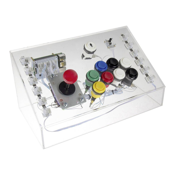
After connecting the power-adapter to the electric socket, the devices is starting automatically. For cable lead-through, please find the opening on the backplate of the arcrylic wall. How to boot or shut down the device is described in the part: Arcade-Gamestation Boot/Shut down [Page14] Ausgabe 18.01.2017... - Page 6 Arcade-GameStation 3.1 Control The following image is showing the button assignment of the Joy-IT Arcade-Gamestation. Pressing the buttons is simulating a keyboard-input of the assigned button. (So the green button simulates the input-number 5). This is important when configuring the configuration of emulators and their button-assignments.
- Page 7 Arcade-GameStation 3.1 Control *Some emulators are using this combination for more functions (e.g.: insert coin) Ausgabe 18.01.2017 Copyright by Joy-IT...
- Page 8 The preinstalled RetroPie-system is intended to be controled with a gamepad/joystick. Therefore ist very easy to use this with the build-in control of the Gamestation. Please note the following button assignment for navigating through the menu: Navigation Confirm Cancel Ausgabe 18.01.2017 Copyright by Joy-IT...
- Page 9 Depending on the transfered Roms (see: Copying ROM-Files / installing games), you can choose the desired system by pressing „left“ or „right“ and confirm your choice with the red button to open the game-list. You will also find, besides the installed emulator-systems, „RetroPie“ in the main menu. Ausgabe 18.01.2017 Copyright by Joy-IT...
- Page 10 „command line— like“ interface. You can still navigate with the joystick-control. The red button acts as „Enter-Button“ and the combination of both white buttons acts as „Escape-Button“ [Combination-> press both buttons simultaneous]. Enter Ausgabe 18.01.2017 Copyright by Joy-IT...
- Page 11 But you won‘t need this for most of the games. 3.3 RetroPie Network settings To communicate with the Arcade-Gamestation in a network, you have to integrate it to your existing home network. You can either connect it with a normal RJ45 network-cable to your router or you can connect it wireless by WiFi.
- Page 12 3.3 Network settings After integrating the Gamestation to your network, you can see the current IP- Networkaddress at „Show IP“. You will need the IP-Address later to transfer new ROM-Files. In this case, the IP-Address is: „192.168.1.236“ Ausgabe 18.01.2017 Copyright by Joy-IT...
- Page 13 Arcade-GameStation 3.4 RGB-LED Light-control A stripe of 8mm RGB-LEDs is mounted around the case of the Arcade-Gamestation. This stripe, when active, is configured to play a lightshow of multiple colors. The currently active lightshow is changeable by adjusting the rotary-potentiometer at the top- right corner.
- Page 14 4.1 Copying ROM-Files / installing games When the Arcade-Gamestation is connected to your network, you can start copying your ROM-Files by entering the IP-Address in a Windows-Explorer window. You can check the mentioned IP-Address, as described under note 3.2, at „Show IP“ in the RetroPie-Configurationmenu.
- Page 15 In most cases you have to copy the ROM-Files as a zipped file (not unzipped) into the folder. After restarting the Gamestation, a new emulatiion-system should be available in the main menu which contains the gamelist of the copied ROM-Files. Ausgabe 18.01.2017 Copyright by Joy-IT...
- Page 16 They often describe how to complete your ROM-File. The Arcade-Emulators of the RetroPie-System are prepared for different Romsets. You can find further informations about this and where to copy the ROM-Files in the RetroPie-Documentation here: https://github.com/retropie/retropie-setup/wiki/Managing-ROMs Ausgabe 18.01.2017 Copyright by Joy-IT...
- Page 17 „Retropie -> RetroPie-Setup -> Manage packages -> main -> ***Emulator Name ***–> Install from binary“ All other emulators also the RetroPie software is published under the GPLv2 or the MIT- license. You can find a copy of the license in the filesystem at: „/home/pi/License/“ Ausgabe 18.01.2017 Copyright by Joy-IT...
- Page 18 (e.g.: it might be helpful to change the used emulator-software due to a higher compatibility) Exit emulator Most emulators can be exited with the „Exit-Hotkey“ combination. Press the three following buttons: [Buttons with the number 4+8+9] Ausgabe 18.01.2017 Copyright by Joy-IT...
- Page 19 After inserting a coin, you can start the game with the start-button.. Exit the Mame4ALL Emulator You can not exit a Mame4ALL-Game with the usual „Exit Hotkey“ combination. Press both white buttons simultaneously to exit this emulator. Ausgabe 18.01.2017 Copyright by Joy-IT...
- Page 20 The Mame4ALL[Arcade]-Emulator might, depending on the game, need some additional configuration. To perform these configurations, press the following combination: The following menu should appear. You can navigate just like in chapter 3.2 for the command-line setup (Red button: Enter—White Button: Escape). Ausgabe 18.01.2017 Copyright by Joy-IT...
- Page 21 If you want to change the button-assignment, you can do this on any computer by entering the IP-Address of your Arcade-Gamestation in your browser. A website will open up which allows you to configure every button. It also allows you to use multiple GPIO-PINs to assign a button-combination.
- Page 22 Arcade-GameStation 6. Assembly instructions Assembly instructions Ausgabe 18.01.2017 Copyright by Joy-IT...
- Page 23 Arcade-GameStation 6. Assembly instructions If you have purchased the Arcade-Gamestation as a construction set, you have to assemble it by using the following instruction. If any problems or difficulties should appear while assembling, we are glad to help you in a friendly call. You can reach us by phone under: 02845/936050 (german...
- Page 24 Arcade-GameStation 6. Assembly instructions *The micro-switches, which belong to the buttons, are not listed separately ** The 12 LinkerKit-RGB-LEDs are already glued to the arcrylic-case Ausgabe 18.01.2017 Copyright by Joy-IT...
- Page 25 To mount the potentiometer, take a screw [B] and a nut [G]. Stick the screw [B] through the hole. On the other side, screw down the nut [G] and repeat this step with the other three screws. Next, place the potentiometer on the screws and mount it with four nuts [G]. Ausgabe 18.01.2017 Copyright by Joy-IT...
- Page 26 Take the button with the player-symbol and stick it through the hole. Turn the case and screw down the button with the nut. Repeat this process with the other buttons. Please note the colors and the orientation of the buttons: Ausgabe 18.01.2017 Copyright by Joy-IT...
- Page 27 Press the microswitch to the right and press the upper hole of the microswitch down and stick it into the plastic-pin. Repeat this step with the other buttons. Make sure that, while placing the buttons, the microswitches don‘t impede each other. Ausgabe 18.01.2017 Copyright by Joy-IT...
- Page 28 Place the joystick from below on the screws, take a washer [H], place it on the screw, take a nut [F] and screw it tight. Repeat this process with the other three screws. Ausgabe 18.01.2017 Copyright by Joy-IT...
- Page 29 When the joystick is mounted, replace the black plate and screw on the head. You can also cover the thread with some glue before screwing the head after mounted it in the acrylic-case. This will fix the head but unmounting the joystick will not be possible anymore. Ausgabe 18.01.2017 Copyright by Joy-IT...
- Page 30 Please see the right image below to find out which buttons you have to connect in which way. Connect the signal-plugs on the center contacts. The ground-plugsare conntected to the bottom contacts of the microswitches. Ausgabe 18.01.2017 Copyright by Joy-IT...
- Page 31 Ground Signal-plug Do the same process with the remaining signal-plug but connect it to the centered contact of the next button. Repeat this process with the other buttons. Ausgabe 18.01.2017 Copyright by Joy-IT...
- Page 32 Ground Signal-plug 1 The signal-plug 1 and the ground-plug are remaining—fix those with a cable tie. There are also contacts beneath the joystick. The two ground-plugs are connected this way on the curved contacts : Ausgabe 18.01.2017 Copyright by Joy-IT...
- Page 33 Step 6 | Installation of the potentiometers signalcable and the RGB-LEDs Next, take one of the two cables which have a white connector on both sides and connect it to the connection of the potentiometer. Ausgabe 18.01.2017 Copyright by Joy-IT...
- Page 34 The first arrow is starting at the first LED and shows in the direction of its next LEDs. Step 7 | Installation of the microSD-Card Plug in the microSD-Card into the Raspberry Pis slot. Ausgabe 18.01.2017 Copyright by Joy-IT...
- Page 35 To mount the Raspberry Pi, take the spacers [J] first. Stick them through the four yellow borderer holes on the board. Screw another four spacers [E] on the spacers from below afterwards. Mount the baseboard with four screws [D]. Ausgabe 18.01.2017 Copyright by Joy-IT...
- Page 36 Arcade-GameStation 6. Assembly instructions You have to place the cable ends on the baseboard. Which end belongs to which port is shown below: Ausgabe 18.01.2017 Copyright by Joy-IT...
- Page 37 Connect the Gamestation, as seen in chapter 2, with a HDMI-cable to a monitor or TV and with the microUSB-power-supply to power. An USB-keyboard and USB-mouse is needed for the first startup. Connect them to the Raspberry Pi. Ausgabe 18.01.2017 Copyright by Joy-IT...
- Page 38 Press the combination „CTRL+ALT+F4“ on your keyboard to enter the command line. Enter the following command and confirm with „Enter“. sudo pkill –9 –f GPioneer.py The output will confirm this with „Killed“. Afterwars, enter the following command and confirm with „Enter“. sudo python /home/pi/ArcadeGamestationApps/buttonchecker/buttonchecker.py Ausgabe 18.01.2017 Copyright by Joy-IT...
- Page 39 Please make sure that the upper white playerbutton has the pin-number 5. If this is not the case, please check your wiring. After reading the pin-numbers for each button, exit the program with the combination „CTRL+C“. Ausgabe 18.01.2017 Copyright by Joy-IT...
- Page 40 KEY_8 PLAYER KEY_9 WHITE_UP + BLACK_DOWN KEY_G BLACK_DOWN + BLACK_UP Poweroff WHITE_DOWN + WHITE_UP KEY_ESC RED + BLACK_UP KEY_TAB Step 11 Back in the command line, enter the graphic interface with the following command: startx Ausgabe 18.01.2017 Copyright by Joy-IT...
- Page 41 Arcade-GameStation 6. Assembly instructions Start the internet browser and enter the following address 127.0.0.1:80 and confirm with „Enter“. This will open up the configuration-window of GPioneer. Ausgabe 18.01.2017 Copyright by Joy-IT...
- Page 42 Also watch the combination-buttons (e.g.: whiteAchten Sie auch auf die Kombinationstasten. They also might need to be adjusted. Afterwars, click on the „Menu“-Button and choose „Shutdown -> Reboot“. After restarting, the assembly is finished and your Arcade-Gamestation is ready. Ausgabe 18.01.2017 Copyright by Joy-IT...
- Page 43 We do not assumbe liability for failures, data loss or incompleteness. Please make data backups in regular intervals. Declaration of conformity As manufacturer, we, the Joy-IT Europe GmbH, declare that our prodcut RB- Gamestation is meeting the requirements, during operation according to regulations, under the following terms:...
- Page 44 Additional three free assignable buttons Resolution 320x240 Interface SPI Colors: 65.536 Backlight: LED Joy-IT SensorKit X40 Comprehensive sensor-set with 40 sensors including analog– and voltage-converters High-Quality, reliable sensors Universal usable including detailed description (including programming-...
- Page 45 Analog signal output and power supply through the über LinkerKit-wiring Linker Kit Board with Hallsensor / Magnetsensor This board contains a hall-sensor which detects magnetic fields. Breakout-Board with hallsensor Allegro A1101 LED for operation-control Ausgabe 18.01.2017 Copyright by Joy-IT...
- Page 46 Operating Temperatur: -30 to +70 °C Linker Kit Board with slide-potentiometer Sensitiv analog inputs between 0V and Vcc are possible with this potentiometer. Breakout-Board with linear slide-potentiometer, distance 40 mm LED controllable by another PIN Ausgabe 18.01.2017 Copyright by Joy-IT...
- Page 47 Linker Kit board with light-sensor The breakout-board is equipped with a light-sensor and a signal amplifier. Analog signal output proportional to the surrounding brightness Ausgabe 18.01.2017 Copyright by Joy-IT...
- Page 48 If there are any further questions or problems, we can help you by mail, phone or by our ticket-supportsystem. E-Mail: service@joy-it.net Ticket-System: http://support.joy-it.net Phone: +49 (0)2845 98469 – 66 (11- 18 Uhr) Find latest manuals here: Find latest downloads here: http://anleitung.joy-it.net http://downloads.joy-it.net For further informations, please visit our homepage www.joy-it.net Arcade-GameStation Ausgabe 18.01.2017 Copyright by Joy-IT...
Need help?
Do you have a question about the Arcade-GameStation and is the answer not in the manual?
Questions and answers