Advertisement
• Optically-isolated I/O
• 8 configurable digital inputs 24VDC ±25%
• 8 configurable digital outputs 24VDC ±25%
• 4 NO relay outputs, 5A max, V=250V/30Vdc, cosϕ=1 resistive load
• 4 analog inputs, configurable via software (V, I, TC, RTD, potentiometer
strain-gauge) 16 bit A/D conversion
This section contains the instructions necessary for correct
installation of the GILOGIK II into the machine control panel
or the host system and for correct connection of the system
power supply, inputs, outputs and interfaces.
Before proceeding with installation read the following
warnings carefully!
Remember that lack of observation of these warnings
could lead to problems of electrical safety and electroma-
gnetic compatibility, as well as invalidating the warranty.
Qualified staff
the installation and use of the system and components are only reserved
at qualified staff.
Conform use
the system and relative components are usable exclusively to the use
previewed in the manual
In order to guarantee a correct and sure operation are indispensable that
the product comes transported, stored correctly, installed, and controlled
second the previewed modalities.
Suitable for use in pollution degree 2 environment. Open type equipment.
Notes Concerning Electrical Safety and Electromagnetic
Compatibility:
• CE MARKING: EMC Conformity (electromagnetic compatibility)
D
IGITAL INPUTS
• 8 optically-isolated digital inputs at 24VDC ± 25% with > 2KV isolation
• Maximum input voltage: 32V 25mA
• Polarity inversion protection
• Maximum voltage for "0" (input OFF) = 5Vdc
• Minimum voltage for "1" (input ON) = 11VDC compatible with devices type 1,3
• Inputs 1 to 4 with 50 kHz pass band
• Inputs 4 to 8 with 5 kHz pass band
• Board has 3 counting units assignable to inputs 1 to 4 configurable as:
- Bi-directional, mono-directional encoder with or without zero mark and
internal speed calculation.
80144_MHW_R-MIXR_1109_ENG
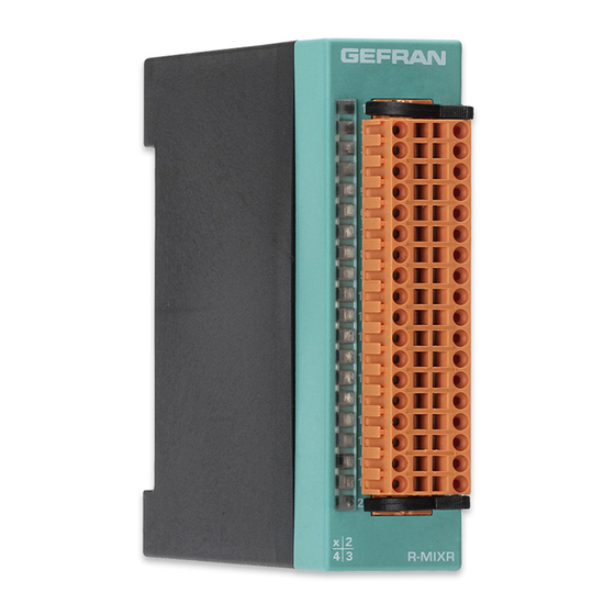
R-MIXR
MODULE WITH 8 INPUTS + 8 DIGITAL OUTPUTS / 4 RELAYS + 4 INPUTS
+ 2 16 BIT ANALOG OUTPUTS + 2 CT
INSTALLATION AND OPERATION MANUAL
cod. 80144 / Edit 01 - 11/09 - ENG
1 • MAIN FEATURES
I
2 • INSTALLATION AND CONNECTION
3 • TECHNICAL DATA
I
• 2 configurable analog outputs (±10V, ±20mA) 16 bit D/A conversion
• 2 CT inputs 16 bit A/D conversion
• Protected against polarity inversion, overload and overtemperature
• LED power supply diagnostics, I/O, module status and alarm
• Extractable connectors supplied
in accordance with EEC Directive 2004/108/CE. The GILOGIK II
system is mainly designed to operate in industrial environments,
installed on the switchboards or control panels of productive process
machines or plants.
Norm of applicable product EN 61131-2.
The Declaration of conformity is available on GEFRAN web:
www.gefran.com
• BT Conformity (low tension)
in accordance with Directive LVD 2006/95/CE.
Advice for Correct Installation for EMC
Inputs and outputs connection
• The externally connected circuits must be doubly isolated.
• To connect the analogue inputs the following is necessary:
- physically separate the input cables from those of the power supply, the
outputs and the power connections.
- use woven and screened cables, with the screen earthed in one point
only.
GEFRAN S.p.A. declines all responsibility for any damage
to persons or property caused by tampering, neglect,
improper use or any use which does not conform to the
characteristics of the controller and to the indications
given in these Instructions for Use.
- Pulse counter
- Measurement of period, frequency, duty cycle
- Measurement of high/low pulse duration
D
IGITAL OUTPUTS
• 8 optically-isolated PNP outputs at 24VDC ± 25% with > 2KV isolation
• Organization: 1 group of 8 outputs
• Output power supply: 24VDC ± 25%
• Max. current for 8 outputs: 6A
• Max. current for group of 4 contiguous outputs (1...4 / 5...8): 3A
• Maximum current per output: 1A,
• Output overload protection trips at 1.2A.
1
Advertisement
Table of Contents

Related Manuals for gefran R-MIXR


Summary of Contents for gefran R-MIXR
- Page 1 Norm of applicable product EN 61131-2. The Declaration of conformity is available on GEFRAN web: Before proceeding with installation read the following warnings carefully! www.gefran.com...
- Page 2 3 • TECHNICAL DATA • Overvoltage on output for 1ms max.1kV • Power supply for strain-gauge supplied by module 10V max 150mA • Outputs 1 and 2 configurable in PWM (10 bit resolution) and in frequency (total for all channels). (32 bit resolution).
- Page 3 +AIN2 Green led Out4 GNDR1 GNDR2 Green led Out5/ROUT1 Green led Out6/ROUT2 Green led Out7/ROUT3 VP_RTD3 VP_RTD4 Green led Out8/ROUT4 -AIN3 -AIN4 +AIN3 +AIN4 Green led RUN GNDR3 GNDR4 Red led ALARM R-MIXR UPPER LOWER CONNECTION CONNECTION LOWER CONNECTION 80144_MHW_R-MIXR_1109_ENG...
- Page 4 4 • INSTALLATION AND CONNECTIONS The connections of the module call for: UPPER CONNECTIONS: Digital inputs/configuration table External power supplies: • 24VDC ±25% 200mA max. plus the current nee- ded to load the outputs. Use unipolar cable with max section 1 mm .
- Page 5 4 • INSTALLATION AND CONNECTIONS 80144_MHW_R-MIXR_1109_ENG...
- Page 6 5 • CONNECTIONS GEFRAN spa via Sebina, 74 - 25050 Provaglio d’Iseo (BS) Tel. 03098881 - fax 0309839063 - Internet: http://www.gefran.com 80144_MHW_R-MIXR_1109_ENG...
Need help?
Do you have a question about the R-MIXR and is the answer not in the manual?
Questions and answers