Table of Contents
Advertisement
Available languages
Available languages
Advertisement
Chapters
Table of Contents

Related Manuals for Pioneer SDA-BS900


Summary of Contents for Pioneer SDA-BS900
- Page 1 SDA-BS900 BLIND SPOT DETECTION / LANE CHANGE ASSIST SYSTEM Instruction Manual and Installation Guide Important (Serial number) The serial number is located on the bottom of the main unit. For your own security and convenience, be sure to record the number.
-
Page 2: Table Of Contents
Contents Thank you for buying this Pioneer product. Please read through these instructions so you will know how to operate this product properly. After you have finished reading the instructions, keep this document in a safe place for future reference. -
Page 3: Precaution
FEDERAL COMMUNICATIONS COMMISSION SUPPLIER'S DECLARATION OF CONFORMITY Product Name: BLIND SPOT DETECTION / LANE CHANGE ASSIST SYSTEM Model Number: SDA-BS900 Responsible Party Name: PIONEER ELECTRONICS (USA) INC. SERVICE SUPPORT DIVISION Address: 2050 W. 190TH STREET, SUITE 100, TORRANCE, CA 90504, U.S.A. Phone:... -
Page 4: Important Safety Information
- If the unit comes loose while you are driving, it may cause an accident. ・Pioneer does not recommend that you install this product yourself. This product is designed for professional installation only. We recommend that only authorized Pioneer service company personnel who have specialized training and experience in mobile electronics set up and install this product. -
Page 5: After-Sales Service
(The sensor heads are waterproof with IP65 rating) ・Do not disassemble or modify this product, as there are high-voltage components inside that may cause an electric shock. Be sure to consult your dealer or the nearest authorized Pioneer service company for internal inspection, adjustments or repairs. -
Page 6: Alert Conditions
Under certain driving scenarios, the SDA-BS900 may detect objects in an unintended way. The following conditions below are examples of scenarios... -
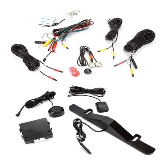
Page 7: Item List
2. When your vehicle is reversing and the system detects an object or vehicle approaching from your left, the Left LED indicator will illuminate and remain illuminated and the included speaker will beep repeatedly. Note: The system will not detect or warn of standing objects or objects moving under 5 mph (8 km/h). -
Page 8: Installation Diagram
Installation Diagram Note: If you cannot connect to the rear tail lamp (turn signal lights combined with brake lights), then connect at the front fuse box. -
Page 9: Wire Connection Diagram
Wire Connection Diagram Right sensor Left sensor ② ① ③ ④ ⑤ ⑮ ⑥ FUSE (2 A) ① Left sensor cable - 1.6 ft (50 cm) ⑭ ② Right sensor cable - 1.6 ft (50 cm) ⑬ ③ Left sensor connector - 5.5 ft (170 cm) ⑦... -
Page 10: Installation Guide
Installation Guide WARNING ・For professional installation only by personnel with specialized training and experience in mobile electronics. ・ Do not install the LED Indicators where it may (i) obstruct the driver's vision, (ii) impair the performance of any of the vehicle's operating systems or safety features, including air bags or hazard lamp buttons or (iii) impair the driver's ability to safety operate the vehicle. -
Page 11: Step 1: Sensor Heads Installation
Step 1: Sensor heads Installation Mounting Radar Pucks with Provided Adjustable Brackets: 1) Prepare Materials brackets and radar heads (see Fig 5). 2) Mount the sensor module on the bracket with screws of the assemble bag (see Fig 6). 3) After found angle is set, firmly screw or bolt the bracket to the car (see Fig 7). Fig 5 Fig 6 Fig 7... -
Page 12: Step 2: Left/Right Turn Signal Installation
Once verified, connect the left and right turning signal wires to the appropriate corresponding input wires of the SDA-BS900 wire harness (see Fig 18, Fig 19, Fig 20). Turn signal inputs of SDA-BS900 is +12VDC only (not switchable to -12VCD); please check with a voltage multi-meter. -
Page 13: Step 3: Led Indicator Installation
Fig 18 Fig 19 Fig 20 Step 3: LED Indicator Installation Install the Left LED indicator and Right LED indicator in a location that is visible to the driver, ideally in or around the vehicle's A-pillars (see Fig 21, Fig 22). Place the LED indicators away from the side curtain air bags, so as not to hinder the deployment of airbag function. -
Page 14: Step 5: Gps Antenna Installation
Step 5: GPS Antenna Installation When installing the GPS Antenna, make sure it is not obstructed by any panels inside the vehicle (see Fig 24). Fig 24 Step 6: Wires Installation ・ Soldering all wiring is recommended. Securely tape and insulate all connections soldered. ・Secure all wires neatly to hide and prevent wire pinch. -
Page 15: Technical Specifications
Technical Specifications Detection Range 70 degrees ( Horizontal Speed Range 0.5 mph (-36 km/h) 37 mph (60 km/h) ~ < 0.5 mph (0.8 km/h) Speed Accuracy Approached by vehicles, Following by vehicles, Overtaking vehicles Direction of Movement Detection Range -6.5 ft (-2 m) ~ 82ft (25m) Operating Voltage 9~18V Radar sensor: IPX6/IPX7... -
Page 16: Troubleshooting
Troubleshooting Reasons Solutions Issues Incorrect connection or pins Check the harness and make LED light does not not making contact sure connection is correct work LED light is broken Replace LED light Make sure the LED indicator with RED color is on driver side and YELLOW is on the passenger side, Microwave sensor or LED Opposite LED... - Page 17 SDA-BS900 DÉTECTION DES ANGLES MORTS / SYSTÈME D'ASSISTANCE AU CHANGEMENT DE VOIE Manuel d'instructions et guide d'installation Important (numéro de série) Le numéro de série se trouve au bas de l'unité principale. Pour votre propre sécurité et commodité, assurez-vous d'enregistrer le numéro.
- Page 18 Table des matières Merci d'avoir acheté ce produit Pioneer. Veuillez bien lire ces instructions afin de faire fonctionner votre appareil correctement. Suite à la lecture de ces instructions, conservez ce document dans un endroit sûr pour références ultérieures. Précaution ..............19 Informations aux clients ............19...
-
Page 19: Précaution
DÉTECTION DES ANGLES MORTS / SYSTÈME D'ASSISTANCE AU CHANGEMENT DE VOIE Numéro de modèle: SDA-BS900 Nom du parti responsable: PIONEER ELECTRONICS (USA) INC. DIVISION AU SUPPORT ET SERVICES Adresse: 2050 W. 190TH STREET, SUITE 100, TORRANCE, CA 90504, U.S.A. Téléphone:... -
Page 20: Informations Importantes Sur La Sécurité
ATTENTION ・Conditions particulières des véhicules à considérer Pendant le démarrage et l'initialisation de l’appareil, ce dernier peut prendre jusqu'à 2 minutes pour établir une connexion GPS. Si le véhicule est conduit avant qu'une connexion GPS ne soit établie ou si la connexion GPS est interrompue (à... -
Page 21: Service Après-Vente
P.O. Box 1720 Long Beach, CA 90801-1720 Garantie limitée de trois ans Lorsqu'il est acheté auprès d'un marchand autorisé Pioneer, cet appareil est couvert par la garantie limitée de trois ans de Pioneer. Veuillez visitez http://pioneerelectronics.com/warranty pour examiner et télécharger les informations détaillées et conditions de la garantie limitée. Vous pouvez aussi demander une copie en appelant 1-800-421-1404 ou en écrivant à... -
Page 22: Conditions D'alerte
à votre gauche et à votre droite. ATTENTION Le SDA-BS900 peut non seulement détecter les objets s’approchant de votre véhicule, mais également détecter les objets que votre véhicule approche ou dépasse. Dans certains scénarios de conduite, le SDA-BS900 peut détecter des objets de manière inattendue. Les conditions suivantes ci-dessous sont des exemples de scénarios dans lesquels des notifications d'erreur peuvent survenir. - Page 23 2. Si le clignotant gauche de votre véhicule est activé lorsqu'un objet ou un véhicule approche, ou votre véhicule approchant / dépassant d'autres véhicules à l’arrière, le témoin DEL gauche clignotera à plusieurs reprises et le haut-parleur (inclus) émettra un avertissement sonore. D.
-
Page 24: Liste Des Articles
Liste des Articles Image Quantité Numéro Nom de l'article Capteur radar Harnais principal 1 paire 1 paire Câble d’extension DEL Module d’interconnexion GPS Témoins indicateur à DEL 1 paire Lentilles additionnelles pour 2 paire témoin DEL avec collant bifaces Antenne GPS Haut-parleur Outil d'angle d'installation 1x Foret... -
Page 25: Schéma D'installation
Schéma d'installation Note: Si vous ne pouvez pas vous relier aux clignotants (feux de signalisation de virage combinés avec des feux de freinage), vous pouvez toujours utiliser l’information à la boîte de fusible. -25-... -
Page 26: Schéma De Raccordement
Schéma de raccordement Capteur droit Capteur gauche ② ① ③ ④ ⑤ ⑮ ⑥ Fusible (2 A) ① Câble de capteur gauche - 1.6 pieds (50 cm) ② Câble de capteur droit - 1.6 pieds (50 cm) ⑭ ③ Câble de capteur gauche - 5.5 pieds (170 cm) ④... -
Page 27: Guide D'installation
Guide d'installation AVERTISSEMENT ・Pour installation professionnelle uniquement par un personnel ayant une formation spécialisée et une expérience dans l'électronique automobile. ・ N'installez pas l'unité témoins DEL où ces derniers peuvent (i) entraver la vision du conducteur, (II) nuire à la performance de l'un des systèmes de gestion ou des dispositifs de sécurité du véhicule, y compris des coussins gonflables ou de contrôle de feux de détresse ou (III) nuire à... -
Page 28: Étape 1: Installation Des Têtes De Capteur Radar
Étape 1: Installation des têtes de capteur radar Installez les capteur radar à l’aide du support réglable inclus; 1) Préparez les supports requis pour les capteurs radar (voir Fig. 5). 2) Fixez le capteur radar sur le support avec les vis du sac d'assemblage (voir Fig. 6). 3) Une fois L'angle correctement ajusté, vissez fermement ou boulonnez le support à... - Page 29 Élévation Avant détecteur détecteur Arrière Rapporteur Rapporteur d’angles d’angles Fig. 10 Fig. 11 Lors de l'installation des capteurs, appliquez le côté métallique à la surface de montage et gardez les deux côtés du capteur perpendiculairement au sol (voir Fig. 12). Pour s'assurer que le capteur est correctement orienté, assurez-vous que le fil sort du côté...
-
Page 30: Étape 2: Connexion Des Informations De Clignotants
Une fois validé, relier les fils des clignotants gauche et droit aux fils d'entrée correspondants du harnais relié à l’unité SDA-BS900 (voir Fig. 18, Fig. 19, Fig. 20). Les signaux en provenance des clignotants doivent être positif (+12Vcc) lorsqu’ils sont actif. -
Page 31: Étape 4: Installation Du Haut-Parleur
Étape 4: Installation du haut-parleur Lors de l'installation du haut-parleur, assurez-vous qu'il n'est pas obstruée par des panneaux du véhicule (voir Fig. 23). NOTE: Pour régler le volume du haut-parleur, basculez le commutateur sur l’intensité désirée; "HI/LOW/OFF". Fig. 23 Étape 5: Installation de l'antenne GPS Lors de l'installation de l'antenne GPS, assurez-vous que celle-ci n'est pas obstruée par des panneaux du véhicule (voir Fig. -
Page 32: Spécifications Techniques
Spécifications techniques Angle de détection 70 degrés (horizontale) Plage de vitesse 0.5 mph (-36 km/h) 37 mph (60 km/h) ~ < 0.5 mph (0.8 km/h) Précision de la vitesse Véhicules en approche, Suivi par des véhicules, Sens du mouvement Dépassement de véhicules Plage de détection -6.5 pieds... -
Page 33: Dépannage
Dépannage Symptômes Raisons possibles Solutions Connexion incorrecte ou Vérifiez le harnais et assurez-vous broches ayant un mauvais Le témoin DEL ne que les connexions sont correcte contact fonctionne pas Remplacez la lumière DEL La témoin DEL est brulé Assurez-vous que l'indicateur DEL avec la couleur Rouge** est du côté... - Page 34 PIONEER CORPORATION 28-8, Honkomagome 2-chome, Bunkyo-ku, Tokyo 113-0021, JAPAN PIONEER ELECTRONICS (USA) INC. P.O. Box 1540, Long Beach, California 90801-1540, U.S.A. TEL: (800) 421-1404 © 2019 Pioneer Corporation.
Need help?
Do you have a question about the SDA-BS900 and is the answer not in the manual?
Questions and answers