
Related Manuals for AOR ARD9900

Summary of Contents for AOR ARD9900
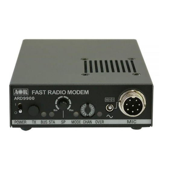
- Page 1 ® ARD9900 FAST RADIO MODEM Multi-Mode and Digital Voice Interface Operating manual AOR, LTD.
- Page 2 Thank you for purchasing the AOR ARD9900 Multimode and Digital Voice Interface. The ARD9900 is designed to convert your HF radio equipment to a multi mode and digital voice capable radio without performing any modifications to your transceiver. Please read through this instruction manual and familiarize yourself with the operation of the ARD9900.
- Page 3 Digital voice communications using existing analog 2 way radios with encryption. The ARD9900 uses the same audio frequencies (300 Hz ~ 2500 Hz) as microphone audio to modulate the voice signal. This allows you to use an analog radio as a digital voice transceiver.
- Page 4 Information to the Digital Device user This equipment uses and can generate radio frequency energy and, if not installed and used in accordance with the instructions, may cause harmful interference to radio communications. However, there is no guarantee that the interference will not occur in a particular installation.
-
Page 5: Table Of Contents
Rear Panel -------------------------------------------------------------------------------------------- 8 Top Panel ----------------------------------------------------------------------------------------------10 Internal View ------------------------------------------------------------------------------------------10 Bottom View -------------------------------------------------------------------------------------------11 Interfacing the ARD9900 -------------------------------------------------------------------------------12 Connection to a Radio ----------------------------------------------------------------------------- 12 Connection to a Microphone --------------------------------------------------------------------12 Connection to a PC ------------------------------------------------------------------------------- 13 Connection to a Power supply ------------------------------------------------------------------ 13... -
Page 6: Supplied Accessories
Supplied Accessories The following items are provided in the box: Accessory Quantity ---------------------------------------------------------------- Microphone PC interface cable Speaker Cable DC Power cable Microphone Connector Instruction manual Controls and functions Front Panel 1 1 1 1 0 0 0 0 1 1 1 1 0 0 0 0 1 1 1 1 |... - Page 7 Set the mode switch to [~] (analog mode). Press and hold this switch to force the ARD9900 to decode digital voice signals. Caution: Frequency tolerance for both parties must be in the range of +/-125 Hz. (Refer to: Operations -- Digital Voice Communication force receive at page 17 for details.)
-
Page 8: Rear Panel
Select the Digital voice mode [10101] or the Analog voice mode [~]. When the Analog voice mode [~] is selected, ordinary analog voice communications will be made. In the receive mode, however, the ARD9900 will automatically detect the mode of the incoming signal and decode signals accordingly. - Page 9 Connect a video monitor to this connector to monitor a received image or a picture to be sent. n. RADIO Connector Using the supplied 8 pin connector, connect the ARD9900 to your radio equipment. You will need to wire a cable according to the microphone connector specifications of your radio.
-
Page 10: Top Panel
5.6 ~6.5 VDC. DO NOT apply 12.0V or severe damage will result, and the warranty will be void! Note: No low battery voltage detector is built-in the ARD9900. Frame ground Top Panel... -
Page 11: Bottom View
w. Internal speaker setting Jumper setting 1 – 2 Activates internal speaker (default) 2 – 3 Disable internal speaker Speaker output is also available from the pin #1 of the microphone connector. (Note: The SP OUT (external speaker output) has priority regardless of the above jumper setting.) x. -
Page 12: Interfacing The Ard9900
Interfacing the ARD9900 Connection to a Radio Before using your ARD9900, you will first need to wire the cable between your radio equipment and the ARD9900. For your convenience, an 8-pin of a microphone connector for the ARD9900 is included. -
Page 13: Connection To A Pc
Taking this pin to the ground will enable to transmit. (Same operation as the TX switch on the front panel.) Taking this pin to the ground will force the ARD9900 to the Digital voice communication mode. When this pin is left open, the operation mode will be set by the mode switch on the front panel. -
Page 14: Level Adjustment
3. Set the mode switch to [10101] (digital mode.) 4. Set the CHANNEL selector to [0]. 5. Press and hold the TX switch, and power on the ARD9900. The STA LED starts blinking indicating the ARD9900 is in the microphone level adjustment mode. -
Page 15: Code Setting
User ID code Setting The User ID code is a unique code for individual ARD9900 units. To change the ID code, first type the [AMA] command to allow the user to go into the Data management Menu. -
Page 16: Air Key Code Setting
Channel Switch Setting There are 16 different channel settings for the ARD9900. By simply rotating the channel switch on the front panel of the ARD9900 to the desired setting, a pre- programmed encryption mode can be easily recalled from the memory. - Page 17 &&&&& Netmask (Current netmask) F: Netmask valid 0: Netmask invalid Communication mode (Displays the communication mode on the channel) 0: Non encryption mode 1: Digital squelch mode Fixed encryption mode 3: Random encryption mode ! ! ! ! ! Other party’s ID (Set other party’s ID) I D: 00000 ~ 99999 @@@@@ Netmask (Set netmask valid / invalid)
-
Page 18: Operations
[ Note: All adjustments must be properly performed before operation.] Voice Communication Your ARD9900 is capable of Digital or Analog Voice Communications. In the receive mode, the ARD9900 will automatically recognize the type of communication, and set itself to the appropriate mode. In the transmit mode, the desirered operating mode can be selected by using the front panel Mode switch. -
Page 19: Receive
Receive Enter the command [ACO] to go into the converse mode. The received valid data will be decoded and displayed on the PC screen. If received data is missing, (which may occur during poor propagation conditions) “garbage” data may be displayed on the PC screen. -
Page 20: Transmit
Transmit When pin - 4 of the microphone connector is grounded, the ARD9900 starts sending an image. When the Video Through Function is activated (AVT command is ON), pressing the TX switch will enable output of the video signal connected to the Video Input also be sent to the video output port, so that you can monitor the video image. -
Page 21: Specifications
Manually selected by pressing the TX switch Analog voice mode: Manually selected by the mode switch Video Compression AOR original JPEG format Video Input/output NTSC or PAL depending on version Power Requirement 10.7 ~ 16 V DC (Approximately 200 mA @ 12 V 6.0 V DC with battery operation ( 5.6 ~ 6.5 V DC) -
Page 22: Type Of Communications And Their Respective Features
Type of Communications and their respective features Encryption Method Using the Master key and algorithm, the encryption table for the data encode is created. Therefore, the Master key and algorithm must be set to the same values for both the transmit and the receive units. The actual encryption code is selected from the encryption table by the Air Key. -
Page 23: Communication Selection Guidance
Communication Selection Guidance The following is a list of communication modes for the ARD9900. Choose the most suitable communication mode for your applications. Factory default setting is the non encryption mode (Communication mode: 0). Communication Mode Setting Function Mode Flag Algorithm Encrpt. -
Page 24: Communication Mode Setting
Communication Mode Setting The communication setting is set into discrete channels. [Procedures] Using the AMA command, enter the System Management Screen. Select the desired channel on the front panel. Using the ACP command, set the desired commnucation mode setting. To verify details of the setting, use the ACP command. ACP [CR] To verify details of the communication channel, use the ADS command. -
Page 25: Detailed Functions Of Communication Mode
Detailed function of communication mode [Caution: Communication mode must be set to the same for transmit end and receive end.] Mode Non encryption mode Features Non encryption. Factory default setting. Force receiving available Setting Flag Algorithm Functions Encrption Squelch Air Key at RX Air Key TX Rolling Code Mode Code... - Page 26 Mode Random Encrption mode 1 Features Communication can be made with the station that has Flag 40 or Flag 50. (The Master key and algorithm must be set to the same value.) Setting Flag Algorithm 00-79 Functions Encrption Squelch Air Key at RX Use the Air Key in the transmit data Air Key TX Send the preset code from the transmit end...
- Page 27 Mode Random Encrption Mode 4 Features Communication can be made with the station that has Flag 40 or Flag 50. (The Master key and algorithm must be set to the same value.) Setting Flag Algorithm 80-99 Function Encrption Squelch Air Key at RX Use the Air Key in the transmit data Air Key TX Send the random coded Air Key from the transmit end...
-
Page 28: Control Commands
(marked as [10101] ) to the serial port of a PC. [NOTE: Be sure your PC’s serial port is active. Check for correct hardware and software settings!] Below are the pin assignments of the COM connector of the ARD9900. ARD9900 COM connector Serial connector of a PC (D-Sub 9 –... -
Page 29: Command Format
Command Format Run a terminal software program, and then turn the power of the ARD9900 on. The following message should appear on the PC screen: CMD> This indicates the ARD9900 is ready to accept commands from the PC. Each command consists of three (3) alphabetical characters. -
Page 30: Operator's Command List
Entering a command without a parameter will display the current parameter (value) setting. CMD>CCC[CR] If an invalid parameter or command is entered, the ARD9900 will respond: CMD> CMD> Operator’s Command List Command Function Send VIDEO In signal to VIDEO OUT (to a monitor screen) Capture image into memory of the ARD9900 Display the last received sender’s ID... -
Page 31: Operator's Command Details
Parameter Send VIDEO In signal to the VIDEO OUT (to the monitor screen) 0: Capture image into memory of the ARD9900 Details While AVT command is OFF, [AAQ 0] will be accepted. Entering AAQ[CR] will respond with the current status. - Page 32 Function Display the last received sender’s ID Default 12356 Format ACS [CR] Parameter None Details Display the last received sender’s ID Example ACS [CR] Function List the current commands Default None Format ADC [CR] Parameter None Details List the current commands Example ADC [CR] Function...
-
Page 33: Command List For The System Manager
After any of the following commands have been changed, the ARD9900 must be turned power off, and then turned back on to reinitialize.] Command Function Set an Air Key code Set the transmit channel... - Page 34 Function Set the transmit channel Default CH: X ID: 00000 NM: 00000 MD: 0 X: The current selected channel Format ACP _ {00000 – 99999} _ {each digit 1/0} _ {80/00/40/50}{00 – 99}[CR] Parameter 00000 – 99999 Other party’s ID (Do not enter any character) Each digit 1/0 Net mask setting 0: Net mask / squelch invalid...
- Page 35 Function Display the current commands Default None Format ADC [CR] Parameter None Details Display the current commands Example ADC [CR] Function List the current commands Default Flag: 80 Algorithm: 00 Air Key: 0000 User ID: 77777 CH: X ID: 00000 NM: 00000 MD: 0 X: The current selected channel Format ADS [CR]...
- Page 36 Function Select to add the LF code followed by the CR to the terminal Default Format ALF {ON/OFF} [CR] Parameter ON: Add LF after CR OFF: Does not add LF after CR Details Select to add the LF (Line Feed) code followed by the CR (Carriage Return) to the terminal Example ALF_ON [CR]...
- Page 37 Function Set the output level of the ARD9900 to the radio Default Format ATT_{ON/OFF} [CR] Parameter ON: Select low level signal output to the radio OFF: Select high level signal output to the radio Details Set the output level of the ARD9900 to the radio...
- Page 38 Manufacturer: AOR, LTD. 2-6-4, Misuji, Taito-Ku, Tokyo, 111-0055, Japan URL: www.aorja.com US distributor: AOR USA, INC. 20655 S. Western Ave. Suite 112 Torrance, CA 90501 Phone: 310-787-8615 Fax: 310-787-8619 URL: www.aorusa.com e-mail: info@aorusa.com April 17, 2013 Printed in Japan...
Need help?
Do you have a question about the ARD9900 and is the answer not in the manual?
Questions and answers