Table of Contents
Advertisement
Quick Links
- 1 Connecting the Solenoids to the Controller (Outputs)
- 2 Inserting Batteries
- 3 Connecting a Rain Sensor, Flow Meter, and Fertilizer Meter
- 4 Main Screen Features
- 5 Establishing Communication with the Server
- 6 Creating an Irrigation Program
- 7 Fault Indication
- 8 Technical Specifications
- Download this manual
Advertisement
Table of Contents

Related Manuals for Galcon G.S.I DC


Summary of Contents for Galcon G.S.I DC
- Page 1 G.S.I DC Controller Installation & User Guide January 2015...
- Page 2 © 2012-2014 Galcon. All rights reserved. Information in this documentation is subject to change without notice and does not represent a commitment on part of Galcon. The software described in this document is subject to the license agreement that is included with the product, which specifies the permitted and prohibited uses of the product.
-
Page 3: Table Of Contents
Table of Contents Introduction ..............6 G.S.I Controller Models ............6 Setting Up the G.S.I Controller ........7 Installing the Controller ............7 Installing on a Wall or in a Control Cupboard ....7 Installing on a Pole ..........10 Establishing the Electrical Connections ......... - Page 4 Pausing and Resuming Irrigation from the Controller ..... 34 Fault Indication ..............35 Locking and Unlocking the Screen ........36 Technical Specifications ..........39...
- Page 5 List of Figures Figure 1: Open Controller Cover ........... 8 Figure 2: Control Panel Swung Outward ......... 8 Figure 3: Opening the Internal Casing ........... 9 Figure 4: Mounting Screw Holes on Back of Unit ......9 Figure 5: Mounting Screw Holes Dimensions ........9 Figure 6: Inserting the Mounting Screws ........
- Page 6 Figure 26: Six Day Cycle Setting Example........29 Figure 27: Start Day Screen Example .......... 29 Figure 28: Start Time Screen ............. 30 Figure 29: OFF Screen ............... 30 Figure 30: OPEN Screen – immediate cycle start ......31 Figure 31: Manual Irrigation Screen ..........32...
-
Page 7: Introduction
1 Introduction The Galcon G.S.I Controller commands the irrigation valves in the field. It is connected wirelessly to the G.S.I web application that enables programming the controller remotely. Creating irrigation programs for the G.S.I Controller is primarily done from the G.S.I web application. However, you can also create a simple irrigation program directly on the controller even before setting up the web application. -
Page 8: Setting Up The G.s.i Controller
G.S.I DC Installation and Operation Guide 2 Setting Up the G.S.I Controller Setting up the G.S.I Controller system includes the following tasks: Installing the Controller (see below) Establishing the Electrical Connections (see page 12) Installing the Controller The controller is designed to withstand outdoor installation conditions (at a rating of IP64). - Page 9 G.S.I DC Installation and Operation Guide 3. For the internal casing on the right side, unscrew the two screws and open the casing (Figure 3). Mount the controller to the wall or to the control cupboard through the marked holes (Figure 4 and Figure 5) with the aid of three screws.
- Page 10 G.S.I DC Installation and Operation Guide Figure 8: Opening the Internal Casing Figure 9: Mounting Screw Holes on Back of Unit Figure 10: Mounting Screw Holes Figure 11: Inserting the Mounting Screws Dimensions...
-
Page 11: Installing On A Pole
G.S.I DC Installation and Operation Guide Installing on a Pole To install the controller on a pole: 1. While maintaining their current orientation in space, remove the screws and the two brackets on the back of the controller. Figure 12: Removing the Pole Mounting Brackets 2. - Page 12 G.S.I DC Installation and Operation Guide 3. Rotate the lower bracket 180 degrees around its horizontal axis. Then reconnect it to the back of the controller using the supplied screws. Figure 14: Lower Bracket Reorientation Note: If the two brackets are correctly oriented, their small flaps will be facing outward and the arrow icons on both will point upwards (see Figure 15).
-
Page 13: Establishing The Electrical Connections
5. Position the unit on the pole and affix it in place by fastening the mounting bands around the pole. Establishing the Electrical Connections The G.S.I DC Controller has the following output connectors: 12 irrigation valves Master valve The G.S.I Controller has the following inputs:... -
Page 14: Connecting The Solenoids To The Controller (Outputs)
G.S.I DC Installation and Operation Guide Connecting the Solenoids to the Controller (Outputs) To connect the solenoids to the controller: Insert the solenoid wires through the cable gland at the bottom of the controller. 2. Connect the wires to the corresponding connectors according to wire color, that is, connect the black wire to the connector labeled B, and the red wire to the connector labeled R. -
Page 15: Inserting Batteries
G.S.I DC Installation and Operation Guide Inserting Batteries The G.S.I DC Controller comes pre-installed from Galcon with a pack of four Lithium batteries (3.6 V each battery and 14.4 V in total). If you need to replace the Lithium pack, contact your Galcon distributor. - Page 16 G.S.I DC Installation and Operation Guide 5. Make sure that the wires of the battery compartment are well connected to the power inlet on the G.S.I card. 6. Insert four Lithium batteries 3.6 V size D. If you cannot obtain Lithium batteries, use four alkaline D-size batteries.
-
Page 17: Connecting A Rain Sensor, Flow Meter, And Fertilizer Meter
G.S.I DC Installation and Operation Guide Connecting a Rain Sensor, Flow Meter, and Fertilizer Meter The GSI unit supports the following input devices: Rain sensor Flow meter (pulse type) Fertilizer meter To connect the input wires: Rain sensor – Connect one of the rain sensor wires to the connector labeled Rs, and connect the second sensor wire to one of the connectors labeled C on the INPUT line. - Page 18 G.S.I DC Installation and Operation Guide Note: Your SIM card definitions should already have been set by the manufacturer. If you are inserting an independent SIM card and you need to set its definitions yourself, refer to the document SIM Card Definitions provided by Galcon.
- Page 19 G.S.I DC Installation and Operation Guide Figure 25: SIM Card Insertion Orientation 6. Close the case cover. 7. Hold the SIM card case cover down while you slide the cover to the side, as indicated by the arrow labeled LOCK (Figure 26).
-
Page 20: On-Site Controller Operation
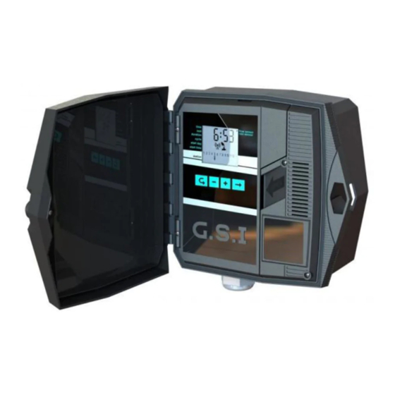
G.S.I DC Installation and Operation Guide 3 On-Site Controller Operation The Galcon G.S.I Controller is designed to run irrigation programs created using the online G.S.I Web User Interface. In addition, however, the G.S.I Controller includes a control panel which enables basic, initial program creation. - Page 21 G.S.I DC Installation and Operation Guide Batteries Communication Condition Synchronizing data Irrigation in progress Station no Master irrigating valve open Figure 27: Main Screen Press to cycle through the following information displays on the Main screen: Current time (hh:mm format) Flow value currently detected by the flow sensor (in m /hr).
- Page 22 G.S.I DC Installation and Operation Guide The Main screen is the launching point for all other G.S.I. controller operations. It displays the following information depending on the circumstances: By default – Displays the current time (hh:mm format) and a list indicating the number of irrigation stations which are currently connected to the controller.
-
Page 23: Establishing Communication With The Server
G.S.I DC Installation and Operation Guide Establishing Communication with the Server To conserve battery power, the DC unit is not constantly in communication with the server. Communication must be established to download programs or upload data logs. Establishing communication with the server automatically sets the controller clock. -
Page 24: Manually Setting The Controller Clock
G.S.I DC Installation and Operation Guide Figure 28: Reception Test Screen To end communication manually: Press and simultaneously. Communication immediately ends. The controller display returns to the Main screen. Manually Setting the Controller Clock In order for the controller to correctly operate the irrigation system at the desired times, the controller clock must first be set correctly. - Page 25 G.S.I DC Installation and Operation Guide To test station operation: 1. Press until the Test screen is displayed (Figure 29). 2. Press and hold until the Test Sequence screen is displayed (Figure 30). The controller automatically begins operating the master station and each of the stations in sequence, for 60 seconds each.
-
Page 26: Creating An Irrigation Program
G.S.I DC Installation and Operation Guide Figure 31: Stop Test Sequence Screen To test the fertilizer: Press mode and – at the same time to open the fertilizer for 15 seconds. Figure 32: Fertilizer Test Screen To test the Master valve: 1. -
Page 27: Setting Irrigation Program Durations
G.S.I DC Installation and Operation Guide Stations always run in the order of their numbers. You can set a different duration for each station. The cycle time, start day, and start time apply for the first station in the sequence. -
Page 28: Setting The Irrigation Cycle Time
G.S.I DC Installation and Operation Guide Figure 33: Duration Screen Example Setting the Irrigation Cycle Time You can set an irrigation program to occur one time only, or to occur repeatedly according to a cycle. When setting a recurring cycle, the cycle value you set defines the length of time (in days) which passes between irrigations program start times. - Page 29 G.S.I DC Installation and Operation Guide Figure 34: Cycle Screen To set cyclical irrigation programs: 1. Press until the Cycle screen appears (Figure 34). 2. Press once. The display changes from “ON CE” to “h 00”, indicating zero hours.
-
Page 30: Setting The Irrigation Start Day And Time
G.S.I DC Installation and Operation Guide Figure 36: Six Day Cycle Setting Example 4. After setting the desired cycle length, press to progress to the next screen, which automatically saves the change. Setting the Irrigation Start Day and Time... - Page 31 G.S.I DC Installation and Operation Guide passed for the current day, the program starts at that time the next day. 2. Press and to increase and decrease the number of days. In Figure 37, the value is set to 10 days. The maximum supported value is 30 days.
-
Page 32: Cancelling An Irrigation Program Start
G.S.I DC Installation and Operation Guide Figure 40: OPEN Screen – immediate cycle start 5. Press to progress to the next screen, which automatically saves the change. Cancelling an Irrigation Program Start To cancel an irrigation program start: 1. From the Main screen, press until the Start Time screen appears. -
Page 33: Initiating Manual Irrigation For A Station
G.S.I DC Installation and Operation Guide Initiating Manual Irrigation for a Station In addition to defining an irrigation program, you can manually initiate any station to begin irrigating. The irrigation is performed for the amount of time defined for that station’s duration in the irrigation program you created using the controller’s direct interface. -
Page 34: Resetting The Controller
G.S.I DC Installation and Operation Guide Resetting the Controller If a technical problem occurs, you may want to reset your G.S.I Controller. To reset the controller: Press the Reset button, located in the top-left corner of the G.S.I Controller’s circuit board. The reset process clears the controller’s RAM, and performs the flowing sequence of operations: a. -
Page 35: Pausing And Resuming Irrigation From The Controller
G.S.I DC Installation and Operation Guide Pausing and Resuming Irrigation from the Controller The controller enables you to pause irrigation. While a pause is in effect, all irrigation programs currently in progress are paused, and any new irrigation programs which were scheduled to start are not started. -
Page 36: Fault Indication
G.S.I DC Installation and Operation Guide Fault Indication If a fault occurs in the system, the controller screen displays the message “FLt” or “FL” and a fault number. Fault Numbers and Definitions Fault Indication Description Message FLt 0 Low flow. -
Page 37: Locking And Unlocking The Screen
G.S.I DC Installation and Operation Guide Locking and Unlocking the Screen The G.S.I Controller enables you to lock the screen, preventing people from editing the unit’s programming until the screen is unlocked. To lock the screen: Press , and at the same time. The screen is locked and displays “= = = =”. -
Page 38: Technical Specifications
12 V external battery optional Cellular modem: Quad band GSM modem integrated (GPRS class 10) for operating in all GSM operators globally. Dimensions: 10.5x24.5x25.5 cm Operating ambient temperature: -10°C to 60°C, 14°F to 140°F Maximum wire run from G.S.I DC controller to Galcon solenoids:... - Page 39 G.S.I DC Installation and Operation Guide DC Wire Run Lengths Wire Size Maximum Distance Feet Meters 1110 1700...
- Page 40 Warranty Period. Any defective Products or part/s, which has been replaced, shall become Galcon’s property. 10. Galcon reserves the right to charge the Customer if any warranty service is requested and carried out but no fault is found in the Product or if such defect/fault is not under Galcon’s Warranty.
- Page 41 The site and services are provided on an AS IS and on available basis without warranties of any kind from Galcon. The use of the Site, the Product and/or the Services is at the Customer sole risk.
Need help?
Do you have a question about the G.S.I DC and is the answer not in the manual?
Questions and answers