Table of Contents
Advertisement
Quick Links
Advertisement
Table of Contents

Related Manuals for Galcon Gal Pro DC


Summary of Contents for Galcon Gal Pro DC
- Page 1 GalPro AC/DC Operating Manual...
- Page 3 Gal Pro Thank you for choosing Galcon’s Gal Pro controller. Galcon Company has invested its comprehensive knowledge, accumulated throughout the years, to develop a new irrigation controller that answers the high demands of agriculture. The controller excels in its new hardware and software. A great deal of emphasis was placed on user friendliness.
-
Page 4: Table Of Contents
Gal Pro Instruction 1.0 Index 1. Preface ..........................5 2. Controller Description ......................6 3. Installation ..........................8 a. Physical connection ....................8 b. Output connection ..................... 9 c. Input Connection ..................... 11 d. Power Supply ......................11 4. First Operation ........................14 5. -
Page 5: Preface
Designed to operate 8 Irrigation valves, Master valve, Fertilizer pump, 2 filters and an Alarm output. Gal Pro is manufactured in two configurations, Gal Pro DC: The controller operates 2 or 3 wires 12VDC Latching solenoids. The controller is operated by 4 * 1.5 volt batteries (installed inside the controller casing) or an external power supply of 12 VDC - disposable dry battery or rechargeable battery of 5-7 Amp.* Hours. -
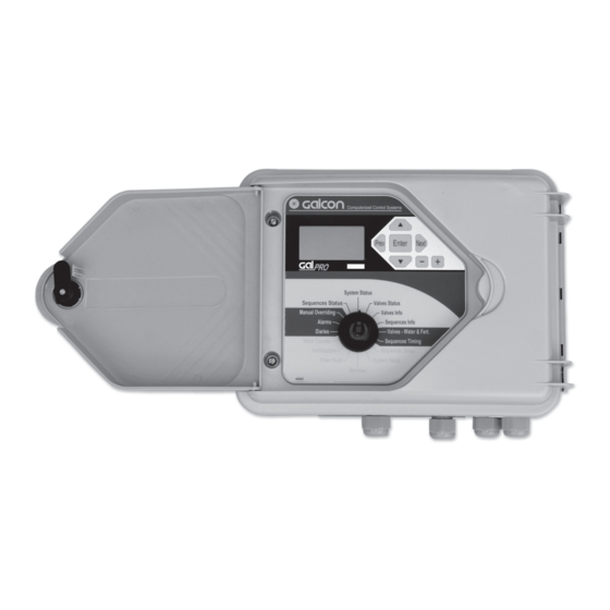
Page 6: Controller Description
Gal Pro Instruction 1.0 2. Controller Description 1. Display 2. Keyboard 3. Menu Selector 1. Display - 5 alphanumeric display rows. The first row shows the current position of the menu. The next 4 rows show information and enable programming. The display is normally off. - Page 7 7. Output Connectors 8. Reset Button on CPU 4. Battery Compartment - 4 * D type 1.5 Volt batteries for Gal Pro DC 5. Power Supply Connectors - Connect the internal batteries or external power supply. Please see the explicit instructions in the Controller Installation chapter.
-
Page 8: Installation
Gal Pro Instruction 1.0 3. Controller Installation Physical Connections The controller is designed to withstand sunny and rainy weather conditions. However it is preferable to provide additional protection from the climate by installing it in a sheltered position. Appropriate installation of the controller will ensure its dependable running throughout the years. The controller can be installed in two ways: •... -
Page 9: Output Connection
2. Insert the solenoid wires via the antigrons on the bottom of the casing and connect them to the detachable connectors. Please make sure that the wires are connected correctly according to their coloring. Three Wire Solenoid Connection for Gal Pro DC. Please Note!!! The wires are connected according to the following order: White... - Page 10 Instruction 1.0 3. Controller Installation Two wire solenoids for Gal Pro DC (black and red wires only) are connected in the same way (the white wire connector is left unconnected). In this way the solenoid is "normally open" i.e. when the output is idle the solenoid sends water.
-
Page 11: Input Connection
It is highly recommended to mark with an indelible pen all of the output functions. 3. Connect all of the detachable connectors. Power Supply to Gal Pro DC Controller As stated in the preface the controller can be powered by 4 * D type 1.5 volt batteries installed in the controller casing or by a 12 VDC external power supply. - Page 12 Gal Pro Instruction 1.0 3. Controller Installation When using an external power supply please use a rechargeable battery of at least 5 amp.* hours connected to a suitable charger. When the controller is located in the vicinity of the power network, you may connect the charger to the network.
- Page 13 Gal Pro Instruction 1.0 3. Controller Installation casing. Connect the battery to the "PWR" connector on the terminal board. Pay attention to the polarity. Solar Panel Charge Controller The "BAT OUT" connector on the terminal board is designed to supply power to an "Amiad" fertilizer pump pulse transmitter or other uses.
-
Page 14: First Operation
Gal Pro Instruction 1.0 4. First Time Operation When connected to the power supply for the first time the following screen appears: The controller initializes (closes) the outputs. This process lasts several seconds, at the end of the initialization the following message appears: Initiate Output: 00 Press Enter to continue Keyboard... - Page 15 Gal Pro Instruction 1.0 4. First Time Operation Menu Selectors The controller menus appear around the 16 state "Menu Selector". They are divided into the following 4 groups: Group A: Irrigation system data - black letters on grey background. Sequence Status - Current information about sequence timing and valve status in the sequence.
-
Page 16: Controller Definition
Voltage and Screen Contrast Definition 1. For Gal Pro DC Move down and skip the following rows: Input Status, Output Status, System Version and Voltage Display. The following row is "battery type". Define the voltage used, 6 Volts if using internal batteries and 12 Volts if using an external power supply. -
Page 17: System Setup Menu
Gal Pro Instruction 1.0 5. Controller Definition e. Output Initialization The controller performs the initialization process automatically when connected to the power. Usually there is no need to perform this process unless you want to technically check solenoids due to replacement. - Page 18 Gal Pro Instruction 1.0 5. Controller Definition Subject Example Explanation Overlap Time Sc. The closing valve closes 10 seconds after the next valve in order to prevent water shock. Pause-Cond.Input If using "condition input" in order to "pause" the whole system, enter the number here.
-
Page 19: Water Meter Menu
Gal Pro Instruction 1.0 5. Controller Definition System Status Water Counter Menu Sequence Status Valve Status Turn the selector to the "Water Counter" menu. Manual Overriding Valve Info Alarms Sequence Info The upper row shows Water Counter No. 1 Diaries Valve •... -
Page 20: Fertilizer System Menu
Gal Pro Instruction 1.0 5. Controller Definition Fertilization Menu System Status Sequence Status Valve Status Turn the selector to the "Fertilzation" menu. Manual Overriding Valve Info Alarms Sequence Info The first row shows Pump Status N.Active Diaries Valve • Water & Fert. Move down until you reach: Fert. -
Page 21: Filter Flush System Menu
Gal Pro Instruction 1.0 5. Controller Definition Filter Flush Menu System Status Sequence Status Valve Status Turn the selector to "Filter Flush" Manual Overriding Valve Info Alarms Sequence Info The first row shows Filtering Diaries Valve • Water & Fert. Move down until you reach: Filter Setup Water Counter Sequence Timing... -
Page 22: Alarm Menu
Gal Pro Instruction 1.0 5. Controller Definition Alarm Menu System Status Sequence Status Valve Status In this menu define whether to automatically cancel alarms and Manual Overriding Valve Info according to which frequency. Alarms Sequence Info Diaries Valve • Water & Fert. Turn the selector to Alarms Water Counter Sequence Timing... -
Page 23: Programming
Gal Pro Instruction 1.0 6. Programming Principle of Irrigation Program Operation The Irrigation Valve The valve is a virtual element that has a physical counterpart that controls the actual valve in the field. It also has a program that specifies the quantities of water and fertilizer. In each valve define the water counter the valve uses and the condition input if necessary. -
Page 24: Valves - Water And Fertilizer Programs
Gal Pro Instruction 1.0 6. Programming Fertilizer Water Fertilization. Segment Water After Water Before Irrigation End Irrigation Start System Status Valves - Water & Fert. Sequence Status Valve Status Manual Overriding Valve Info Turn the selector to Valves - Water & Fert. Menu Alarms Sequence Info In this menu enter the water and fertilizer amounts and the valve... - Page 25 Gal Pro Instruction 1.0 6. Programming Subject Example Explanation Fert.Units L/M3 Via the "+" and "-" keys select one of the options: Liter, Minutes, Ltr/M3, Relate Frt.Flt.React Ignor Via the "+" and "-" keys select one of the options: Ignor - The controller ignores fertilizer faults. Pause - Fertilizer fault stops the irrigation.
-
Page 26: Sequence Setup
Gal Pro Instruction 1.0 6. Programming System Status Sequences Setup Sequence Status Valve Status In this menu define the constants of the sequence for the first time Manual Overriding Valve Info Alarms Sequence Info before programming the sequence. Diaries Valve • Water & Fert. Water Counter Sequence Timing Fertilization... -
Page 27: Sequence Timings
In the case of multiple sequences one has to consider: Gal Pro AC can simultaneously open about 4 irrigation valves, main, fertilizer and filter, as opposed to Gal Pro DC which can open all the outlets simultaneously. -
Page 28: Information And Programming
Gal Pro Instruction 1.0 7. Information and Programming Menus These menus include: System Status Valve Status Valve Info Sequence Status Sequence Info In addition to these menus there are current and accumulating data in the following menus: Water Counters Fertilization system Filter Flush System System Status System Status... -
Page 29: Valve Status
Gal Pro Instruction 1.0 7. Information and Programming Menus System Status Valve Status Sequence Status Valve Status This menu shows the current status of the valves Manual Overriding Valve Info Alarms Sequence Info Diaries Valve • Water & Fert. Water Counter Sequence Timing Fertilization Sequence Setup... -
Page 30: Valve Information
Gal Pro Instruction 1.0 7. Information and Programming Menus System Status Valve Info Sequence Status Valve Status This menu shows the accumulated data for all of the valves. Manual Overriding Valve Info Alarms Sequence Info Diaries Valve • Water & Fert. Water Counter Sequence Timing Fertilization... -
Page 31: Sequence Status
Gal Pro Instruction 1.0 7. Information and Programming Menus System Status Sequence Status Sequence Status Valve Status This menu shows the current status of the sequences. Manual Overriding Valve Info Alarms Sequence Info Diaries Valve • Water & Fert. Water Counter Sequence Timing Fertilization Sequence Setup... -
Page 32: Sequence Information
Gal Pro Instruction 1.0 7. Information and Programming Menus System Status Sequence Info Sequence Status Valve Status This menu shows data from all of the sequences. Manual Overriding Valve Info Alarms Sequence Info Diaries Valve • Water & Fert. Water Counter Sequence Timing Fertilization Sequence Setup... - Page 33 Gal Pro Instruction 1.0 7. Information and Programming Menus System Status Additional General Information Sequence Status Valve Status As previously mentioned, additional general information can Manual Overriding Valve Info Alarms Sequence Info be found in the following different menus: Water Counters, Diaries Valve •...
- Page 34 Gal Pro Instruction 1.0 7. Information and Programming Menus System Status Fertilization Sequence Status Valve Status Manual Overriding Valve Info Alarms Sequence Info Diaries Valve • Water & Fert. Water Counter Sequence Timing Fertilization Sequence Setup Filter Flush System Setup Services Subject Example...
- Page 35 Gal Pro Instruction 1.0 7. Information and Programming Menus System Status Filter Flush System Sequence Status Valve Status Manual Overriding Valve Info Alarms Sequence Info Diaries Valve • Water & Fert. Water Counter Sequence Timing Fertilization Sequence Setup Filter Flush System Setup Services Subject...
-
Page 36: Manual Overriding
Gal Pro Instruction 1.0 8. Manual Overriding System Status Manual Overriding Sequence Status Valve Status This menu shows the following data: Manual Overriding Valve Info Alarms Sequence Info Diaries Valve • Water & Fert. Water Counter Sequence Timing Fertilization Sequence Setup Filter Flush System Setup Services... -
Page 37: Alarm Menu
Gal Pro Instruction 1.0 9. System Alarms System Status The first row of the alarm menus shows the alarm status in the system. Sequence Status Valve Status When everything is okay the message "everything is OK" appears. Manual Overriding Valve Info Alarms Sequence Info During alarms all of the current alarms are listed in this row. -
Page 38: Data Loggers
Gal Pro Instruction 1.0 10. Diaries System Status The diaries menu shows up to 128 last events and alarms. Sequence Status Valve Status Manual Overriding Valve Info Message Date Alarms Sequence Info Diaries Valve • Water & Fert. Message No. Water Counter Sequence Timing Fertilization... -
Page 39: Advance Operation Guide
Gal Pro Instruction 1.0 11. Advanced Operation Flow Control Mechanism The flow control mechanism allows the controller to discover flow deviation. When discovered, the controller performs one of the following according to the definitions: Stops irrigation and issues an alarm. Continues irrigation and issues an alarm. -
Page 40: Condition Input Operation
The following are instructions for the connection and definition of the most widely used condition contacts. If you wish to connect other types of condition contacts please contact technical support at Galcon. Pressure Stat Connection Pressure stat contacts are connected to the pressure line and are designed to sense pressure set points and close a contact during high or low pressure. - Page 41 Gal Pro Instruction 1.0 11. Advanced Operation number. Move to the other sequences and enter the same parameter for all of the sequences that you wish to participate in the pause process. Pressure Differential Switch Connection PD switches are designed to sense the pressure difference between both sides of the filter. Connect the electrical connection of the PD switch (2 wires) to the condition input of the controller.
-
Page 42: Maintenance
It is possible to open several outputs together for a predefined time that is programmed in the Out. Test. Tim-Sc parameter. Changing the Batteries for Gal Pro DC The controller detects the battery voltage. This voltage is displayed in the service menu. When the voltage drops below the required value the controller shows a Low Voltage message. -
Page 43: Technical Specification
Number of Inputs: 8 (4 water counters, 1 fertilizer counter, 3 condition inputs). Analog Inputs: None Input Voltage Gal Pro DC: 6 volts (4 * 1.5 VDC Alkaline D type batteries installed inside the controller). Or 12 VDC battery 5 Amp * H or more connected to a charger or solar panel. - Page 44 Residential Turf & agriculture waterworks Gardening Landscape Galcon Email info@galconc.com Website www.galconc.com...
Need help?
Do you have a question about the Gal Pro DC and is the answer not in the manual?
Questions and answers