Table of Contents
Advertisement
Quick Links
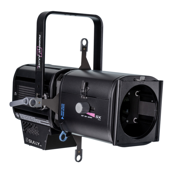
LED PROFILE SPOT /
PROJECTEUR DE DÉCOUPE LED
V1
VALIDATION : 18/11/20
DN41201900
Robert Juliat S.A.S. 32, rue de Beaumont, F 60530 Fresnoy-en-Thelle - phone : +33 (0)3 44 26 51 89 - fax : +33 (0)3 44 26 90 79 - info@robertjuliat.fr
REF
28 - 54°
16 - 35°
11 - 26°
115W LED PROFILE SPOT /
PROJECTEUR DE DÉCOUPE LED 115W
www.robertjuliat.com
Standard
North American
Standard
Nord-Américain
653SX
653CSX
654SX
654CSX
651SX
651CSX
Advertisement
Table of Contents

Subscribe to Our Youtube Channel
Related Manuals for Robert Juliat SULLY 650SX Series


Summary of Contents for Robert Juliat SULLY 650SX Series
- Page 1 PROJECTEUR DE DÉCOUPE LED 115W VALIDATION : 18/11/20 DN41201900 Robert Juliat S.A.S. 32, rue de Beaumont, F 60530 Fresnoy-en-Thelle - phone : +33 (0)3 44 26 51 89 - fax : +33 (0)3 44 26 90 79 - info@robertjuliat.fr www.robertjuliat.com...
-
Page 2: Table Of Contents
6.4 Firmware update ..............................................28 6.5 Factory defaults ...............................................28 6.5.1 Modes ......................................................28 6.5.2 Control ......................................................28 Robert Juliat reserve the right to change or alter any of the items detailed on this page, to increase or improve manufacturing techniques without prior notice. -
Page 3: User's Instructions
1 User’s instructions GENERAL INSTRUCTIONS Not for residential use. These fixtures must only be serviced by a qualified technician. In addition to the instructions indicated on this page, relevant health and safety requirements of the appropriate EU Directives must be adhered to at all times. This fixture is in compliance with section 17 - Lighting appliance for theatre stages, television, cinema and photograph studios. -
Page 4: Presentation
2 Presentation 2.1 Functions Description Identification plates 11. Shutter locking system Data connector (IN and OUT) 12. Lens tube rotation locking button Power connector (IN and OUT) 13. Lens tube access RJ45 network connector 14. Zoom adjustment Handle 15. Front slot for accessories and gel frame holder Safety cable attachment point 16. -
Page 5: Label On Lighting Unit
2.2.2 label on lighting unit Description 1. Model beam angles 2. Net weight (kg) without LED compartment 3. Serial number 4. Class 1 product label 5. Read manual first label 6. European conformity label 7. WEEE directive label 8. Operating positions Units : - Weight = kilogram (kg). -
Page 6: Accessories
2.4 Accessories Reference Description CAV 600A Double slot front cassette for 180x180mm accessories CAV 600AE Double slot front cassette for 185x185mm accessories PCP1716A 16A blue 2P+E 6h IEC60309 power connector PF600M2 185 x 185 mm (7.28 x 7.28 in) metal filter holder G500 180 x 180mm safety grid IWSX755... -
Page 7: Set-Up
3 Set-up 3.1 Mechanics 3.1.1 Operating positions 90° 90° 3.1.2 Minimum distance between a flammable material and the lighting unit 0,80 m / 2.6 ft 5°C 40°C 3.1.3 Instructions for use Minimum : Maximum : 40°F 104°F IP20 - Indoor use only 3.1.4 Hanging •... -
Page 8: Safety Cable
3.1.5 Safety cable • When hung or flown the fixture must be secured by an additional hanging accessory (such as a safety bond or cable) of suitable length. • The combined weight of both the fixture and the accessories must be considered when choosing the load-bearing capability of safety cable or bond. -
Page 9: Data
Power cable Power cable Connector Mains plug Cable type Cable length Wiring Live: Brown Standard 3G1.5 CEE7/7 Neutral: Blue version H07RNF 9.8 ft ® Neutrik powerCON Ground: Yellow/Green TRUE1 TOP North 14AWG Live: Black NAC3FX-W-TOP 1.5 m American SJ TYPE Neutral: White 4.9 ft version... -
Page 10: Art-Net Sacn
3.3.2 Art-Net / sACN • With external switch Protocol Input connector Output connector Art-Net RJ45 sACN Daisy chain: Art-Net sACN Network switch* (*) A 1000 base-T switch that supports IGMP (Internet Group Management Protocol) is necessary if the unit is connected to a network switch to control multiple devices. -
Page 11: Internal Filter Holder
3.4.2 Internal filter holder 3.4.3 Gobo holder / Iris EN - 9 -... -
Page 12: Shutters
3.4.4 Shutters Step 1 Step 2 Step 3 EN - 10 -... -
Page 13: Operations
4 Operations 4.1 Light intensity 4.1.1 Range 100% 4.1.2 Control Remotely with DMX512-A protocol Locally via Standalone mode Art-Net / sACN DMX512-A TSet through RDM protocol or web interface 4.1.3 Parameters 4.1.3.1 Dimming resolution - DMX only T Set through RDM protocol or web interface Resolution DMX mode 8 bits –... -
Page 14: Set Maximum Position
4.1.3.3 Set maximum position T Set through RDM protocol or web interface 100% ----> Maximum (80%) 100% 4.1.3.4 Dimming mode T Set through RDM protocol or web interface Mode Result Without PWM Flicker-Free, perfect for filming PWM 17 kHz Good dimming quality (Default Value) PWM 3,2 kHz Very good dimming EN - 12 -... -
Page 15: Strobe
4.2 Strobe 4.2.1 Range Strobe duration 255 = 20ms 0 = OFF 1 = 1ms Strobe speed 0 = 0.1Hz 255 = 10Hz 4.2.2 Control T Remotely with DMX512-A / Art-Net / sACN protocols Mode 3 – 4 DMX512-A 4.3 Response time 4.3.1 Range X ms DMX 0 = 0 ms... -
Page 16: Beam Size Adjustment
4.4 Beam size adjustment 4.4.1 Range Beam angle Model Minimum angle Maximum angle 653SX / 653CSX 28° 54° 654SX / 654CSX 16° 35° 651SX / 651CSX 11° 26° 4.4.2 Control Focus Zoom 4.5 Orientation 4.5.1 Range Function Range 0 T 360° TILT TU = 0 T 63°... -
Page 17: Control
4.5.2 Control TILT Index 4.6 Colour Fixed colour: Location 1. Front filter holder 2. Internal filter holder Type Standard coloured gel filter Frosted or dichroic glass Dimensions Installation See 3.4.1 See 3.4.2 EN - 15 -... -
Page 18: Beam Shaping
4.7 Beam shaping 4.7.1 Range 4.7.2 Control Locking shutter system Locked Unlocked See 3.4 Accessories for gobo, iris and additional shutters installation EN - 16 -... -
Page 19: Beam Rotation
4.8 Beam rotation 4.8.1 Range Function Range Gobo Shutters 4.8.2 Control EN - 17 -... -
Page 20: Gobos
4.9 Gobos Location Type Metal / Glass A-size Position 1 Position 2 Installation EN - 18 -... -
Page 21: Controls And Parameters
5 Controls and parameters 5.1 Web interface 5.1.1 Control Ethernet connection The fixture must be connected to a compatible network or directly to a computer using an ethernet cable. 5.1.2 Default IP address By defaut : DHCP = OFF Address = 2.XXX.XXX.XXX Mask = 255.0.0.0 T If IP address unknown (due to a previous modification), a hard reset must be done (see 6.5 Factory defaults). -
Page 22: Leds Feedback
5.2 LEDs Feedback 5.2.1 Trouble shooting: • During unit initialisation (power up) – up to 5 seconds: Description DMX OUT DMX IN Network Unit OFF • After initialisation: Unit error DMX OUT DMX IN Network Unit has been reset Display auto-off successfully No ethernet RDM protocol activated... -
Page 23: Dmx512 - A Remote Control
5.3 DMX512 - A remote control 5.3.1 Protocol: E1.11 – 2008, USITT DMX512-A 5.3.2 Configuration: Set mode through web interface Set mode through RDM protocol compatible device 1 - Set DMX address 2 - Set personality mode (see 5.3.4. DMX chart) 5.3.3 Parameters: 5.3.3.1 DMX Hold T Set through RDM protocol or web interface... -
Page 24: Dmx Chart
5.3.4 DMX chart: Mode 1: Mode 2: Mode 3: Mode 4: DMX address Dimmer8B Dimmer16B Profile8B Profile16b Dimmer Dimmer Dimmer Dimmer Dimmer fine Strobe duration Dimmer fine Strobe speed Strobe duration Response time Strobe speed Control mode Response time Control mode 5.3.5 DMX ranges: 5.3.5.1 Strobe duration Range min... -
Page 25: Rdm Remote Control
Product Category PRODUCT_CATEGORY_FIXTURE_FIXED Software Version_ID DMX512 Footprint DMX Personality 1 To X Start Address Sub Device Sensor Count PRODUCT_DETAIL_ID_LIST PRODUCT_DETAIL_LED DEVICE_MODEL_DESCRIPTION SULLY MANUFACTURER_LABEL Robert Juliat DEVICE_LABEL 115W LED PROFILE SOFTWARE_VERSION_LABEL BOOT_SOFTWARE_VERSION_LABEL DMX512 Setup DMX512_PERSONALITY DMX512_PERSONALITY_DESCRIPTION DMX512_STARTING_ADDRESS SLOT_INFO SLOT_DESCRIPTION DEFAULT_SLOT_VALUE Sensors... -
Page 26: Art-Net Remote Control
5.5 Art-Net remote control Artistic Licence Art-Net v3. 5.5.1 Protocol: For more information about Art-Net protocol: http://art-net.org.uk/ 5.5.2 Configuration: Set mode through web interface (see 5.1 Web interface) 1 - If necessary, change IP settings 2 - Set ArtNet parameters : Net / SubNet / Universe 3 - Set DMX address 2 - Set personality mode (see 5.3.4. -
Page 27: Sacn Remote Control
5.6 sACN remote control ANSI E1.31 – 2009 sACN (Streaming-ACN) 5.6.1 Protocol: 5.6.2 Configuration: Set mode through web interface (see 5.1 Web interface) 1 - If necessary, change IP settings 2 - Set sACN universe 3 - Set DMX address 2 - Set personality mode (see 5.3.4. -
Page 28: Service
6 Service 6.1 Preventive maintenance 6.1.1 Frequency General maintenance should be performed at least once a year or more frequently if the equipment is operated in adverse conditions (smoke, heat, humidity, touring, etc.). 6.1.2 General cleaning Remove dust from the unit. Front glasses can be cleaned with solutions containing alcohol. -
Page 29: Analysis
How to remove the Sully LED compartment for cleaning: 1. We recommend you place your luminaire on a flat clean surface. Disconnect from the mains before servicing. 2. Unlock the quarter turn screw with a flat screwdriver. 3. Remove the two screws with a flat screwdriver. 4. -
Page 30: Electronic Thermal Management System
6.3 Electronic thermal management system In case of overheating, light intensity will be reduced by the system. Power reduction and temperature values are available by using a RDM protocol compatible device. 6.4 Firmware update 1. Firmware available on www.robertjuliat.com/profilespots/SULLY_650SX 2. Download and unzip the file 3.
Need help?
Do you have a question about the SULLY 650SX Series and is the answer not in the manual?
Questions and answers