Summary of Contents for Pulsar AWZ 333
- Page 1 PSU-B/A-13,8V/L-3A/1/EL-TR-17Ah/MC AWZ 333 v.2.0 Buffer, linear power supply unit. Installation and operating manual Edition: 2 from the 17 March 2009 Supercedes edition: 1 from the 1 June 2008 10062009...
-
Page 2: Table Of Contents
CONTENTS: 1. Technical description. 1.1. General description. 1.2. Operation principle 1.3. Block diagram 1.4. Description of elements and power supply connectors 1.5. Technical parameters 2. Installation. 2.1. Requirements 2.2. Installation procedure 3. Indication of power supply operation. 3.1. Optical indication 3.2. -
Page 3: Operation Principle
1.2. Operation principle. AWZ 333 is a stabilized transformer power supply unit with a high line regulation. Line voltage ~230V, is lowered with the use of transformer and then it is recertified by a rectifier circuit and a low-pass filter. DC output voltage comes from a line stabilizer. Output voltage is corrected depending on power supply unit operation mode (charging mode battery maintenance). -
Page 4: Description Of Elements And Power Supply Connectors
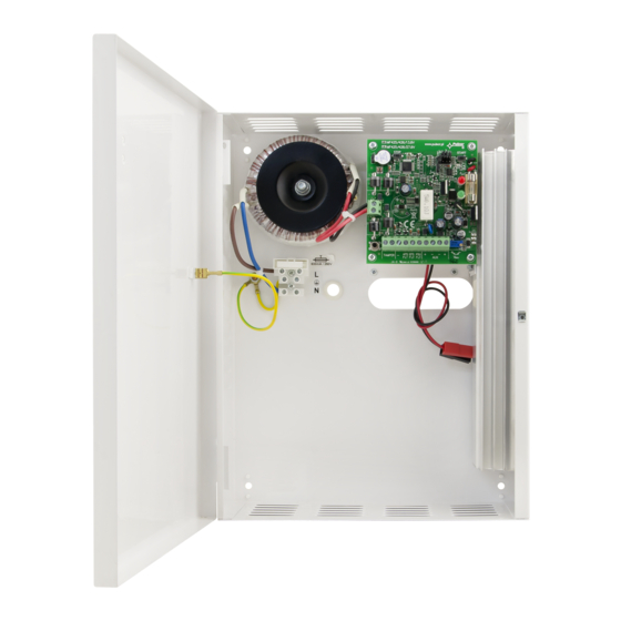
1.4. Description of elements and power supply connectors (fig.2, tab.1, tab.2). Table 1. Element description [fig.2] Acoustic signaling ZB dip-switch STOP button START button Z1, Z2, Z3, Z4 dip-switches OUTPUTS battery RED DIODE optical indication GREEN DIODE optical indication CHARGE dip-switch [10] ~AC~ AC supply connector [11]... - Page 5 Fig.2. The view of the power-supply unit.
-
Page 6: Technical Parameters
1.3. Technical parameters (tab.3) electrical parameters - diagram Uout=f (Io) (fig. 3) (tab.4) mechanical parameters (tab.5) operation safety Table 3. Power supply unit type A, level 1 Supply voltage 230V/AC (-15%/+10%) Supply frequency 50Hz (47÷53Hz) PSU power P 38W max. Current consumption 0,42 A max. -
Page 7: Installation
Table 5. I (first) Protection class PN-EN 60950-1:2004 Protection class IP20 PN-EN 60529: 2002 (U) Electrical strength of insulation between input (network) circuit and output circuits of power-supply 3000 V/AC min. between input circuit and PE protection circuit (I/P-FG) 1500 V/AC min. between output circuit and PE protection circuit (O/P-FG) 500 V/AC min. -
Page 8: Installation Procedure
2 Installation procedure. 1. Before installation make sure that the mains 230 V is disconnected. 2. Install the power supply at the selected place and evacuate connection wires. 3. Remove the main fuse protecting the transformer primary circuit [15]. 4. Connect the supply conductors ~230V to the terminals of the AC 230 V transformer [14]. The earth conductor should be connected to the terminal marked with the grounding symbol [16]. -
Page 9: Indication Of Power Supply Operation
Fig.4. Battery installation procedure. 3. Indication of power supply operation. The device is equipped with optical and acoustic indication of operation. The PSU status can be remotely controlled by two technical outputs. -
Page 10: Optical Indication
3.1 Optical indication. RED DIODE blinking- indication of failure conditions (Tab.6) • GREEN DIODE lit- power supply unit operated from 230 V/AC, normal • operation blinking- shortage of power supply 230 V/AC, • operation from the battery Number of Type of failure Causes Remarks blinks... -
Page 11: Technical Outputs
3.3 Technical outputs. The power supply unit is equipped with indication outputs informing about the power supply shortage and failures. AW – failure output: output (OC type) informing about the failures of the power supply unit. • In the normal state, when there is no failures, the output is closed and it opens if a failure occurs. •... -
Page 12: Power Supply Unit Overload
EU. The power supply unit is adapted for cooperation with the sealed lead-acid battery (SLA). After the operation period it must not be thrown but recycled according to the applicable law. Pulsar K.Bogusz Sp.j. Siedlec 150, 32-744 Łapczyca, Polska Tel.


Need help?
Do you have a question about the AWZ 333 and is the answer not in the manual?
Questions and answers