Advertisement
Quick Links
CALEFFI
www.caleffi.com
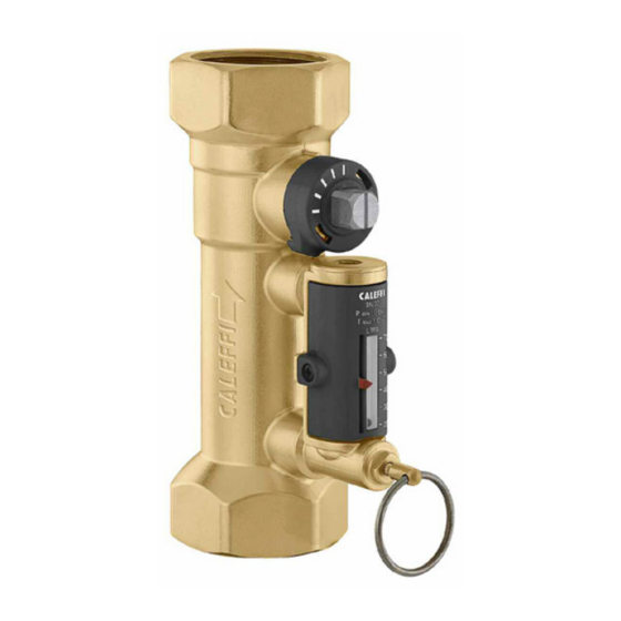
QuickSetter™ Balancing Valve with flow meter
© Copyright 2020 Caleffi
These items are designed for use in
closed hydronic systems. Do not
use in plumbing applications. These
items do not meet the low-lead
plumbing standards of U.S. and
Canada.
Scan to view
·
Installation Tip
Function
The balancing valve accurately controls the flow rate of heating and
cooling transfer fluid supplied to fan coils and terminal units; or where
flow balancing is required in solar thermal systems. Proper hydronic
system balancing ensures the system operates according to design
specifications, providing satisfactory thermal comfort with low energy
consumption.
The flow meter is housed in a by-pass circuit on the valve body and
can be shut off during normal operation. The flow meter permits
fast and easy circuit balancing without added differential pressure
gages and charts. Th balancing valve comes standard with a hot
pre-formed insulation shell to optimize thermal performance for both
hot and chilled water.
Product range
132 S eries
B alanc ing valve with flow meter s izes 1/2", 3/4",
1", 1 1/4", 1 1/2" and 2"
Technical characteristics
Valve
Material:
B ody and ball:
B all c ontrol s tem:
B all s eal s eat:
C ontrol s tem guide:
S eals :
F low meter
Material:
B ody:
Headwork:
Valve s tem:
S prings :
S eals :
Flow meter float and indic ator c over:
Performanc e: Medium:
Max. perc entage of glyc ol:
Max. working pres s ure:
Working temperature range: 14 - 230°F (-10–110°C )
Flow rate range unit of meas urement:
Ac c urac y:
C ontrol s tem angle of rotation:
R equired operating wrenc h:
Threaded c onnec tions :
Flow rate c orrec tion fac tor: 20%-30% glyc ol s olutions :
Ins ulation
Material:
Thic knes s :
Dens ity:
- inner part:
- outer part:
Thermal c onduc tivity (DIN 52612): - at 0°C :
C oeffic ient of res is tanc e to water vapor (DIN 52615):
Working temperature range:
R eac tion to fire (DIN 4102):
e
bras s E N 12164 C W614N
40%-50% glyc ol s olutions :
c los ed c ell expanded PE -X
- at 40°C :
18106.05
132 Series
bras s
c hrome plated bras s
PTFE
PS U
E PDM
peroxide-cured
bras s
c hrome plated bras s
s tainles s s teel
E PDM
PS U
water, glyc ol s olutions
50%
150 ps i (10 bar)
gpm
±10%
90°
1/2"–1 1/4": 9 mm
1 1/2" and 2": 12 mm
1/2"– 2" FNPT
0.9
0.8
10 mm
30 kg/m
50 kg/m
0.038 W/(m·K )
0.045 W/(m·K )
> 1.300
32 - 212 F (0–100°C )
c las s B 2
3
3
Advertisement

Related Manuals for CALEFFI QuickSetter 132 Series


Summary of Contents for CALEFFI QuickSetter 132 Series
- Page 1 18106.05 QuickSetter™ Balancing Valve with flow meter 132 Series © Copyright 2020 Caleffi Function The balancing valve accurately controls the flow rate of heating and cooling transfer fluid supplied to fan coils and terminal units; or where flow balancing is required in solar thermal systems. Proper hydronic...
-
Page 2: Safety Instruction
SAFETY INSTRUCTION This safety alert symbol will be used in this manual to draw attention to safety related instructions. When used, the safety alert symbol means ATTENTION! BECOME ALERT! YOUR SAFETY IS INVOLVED! FAILURE TO FOLLOW THESE INSTRUCTIONS MAY RESULT IN A SAFETY HAZARD WARNING: This product can expose you to chemicals including lead, which is known to the State of California to cause cancer and birth defects or other reproductive harm. -
Page 3: Flow Rate Adjustment
Flow rate The flow rate is adjusted by carrying adjustment out the following operations: A. With the aid of the indicator (1), mark the reference flow rate on which the valve is to be set. B. Use the ring (2) to slowly open the flow meter bypass valve that shuts off the flow of medium in the flow meter (3) under normal operating... - Page 4 D. After completing balancing, release the ring (2) of the flow meter bypass valve, which will automatically go back into the closed position. E. On completing adjustment, the indicator (1) can be used to keep the setting in memory, in case checks need to be made over time.
- Page 5 ∆p (psi) (psi) (bar) (feet of head) Hydraulic characteristics 46.20 at 100% open 23.10 11.55 9.24 6.93 4.62 2.31 0.05 1.16 0.04 0.924 0.03 0.693 0.02 0.462 0.01 0.231 onnection onnection Flow rate (GPM) Flow rate (GPM) 132432 132432 1/2” NPT 1/2”...
- Page 6 CAUTION: Make sure that all the connecting pipework is water tight. 11-8-19 Caleffi North America, Inc. 3883 West Milwaukee Road Milwaukee, WI 53208 T: 414.238.2360 F: 414.238.2366...
Need help?
Do you have a question about the QuickSetter 132 Series and is the answer not in the manual?
Questions and answers